MANY of us see building a car as a laborious process of hand-crafting parts and going through seemingly unending rounds of fitment by trial-and-error. However, the reality is that computers have revolutionised how cars can be built, with new technologies such as 3D scanning capable of radically improving the speed and accuracy of a build.
Three-dimensional scanning has been used across many industries since the early 2000s, including the aerospace, OE automotive, archaeological and medical fields, but now its use is exploding within the realms of street machining and hot rodding. Big American companies like Dynacorn, Edelbrock, ICON 4×4, Art Morrison, Ringbrothers and Roadster Shop all use 3D scanning technology to develop parts.
The basic science of 3D scanning involves a machine running past an object and mapping its shape to build a digital 3D model of that object in the scanner’s software. This model can then be converted for use in computer-aided design (CAD) programs like SolidWorks or Fusion 360. This saves huge time and massively improves accuracy when it comes to designing parts, as an engineer no longer has to custom-draw the model in the CAD software from scratch. A digital 3D model of an object can be created in just a few hours.
The 3D scanning process can be used to create models of full car bodies or frames, complete engines, and even the tiny gears used in a wristwatch (or vintage dash cluster). And the technology is rapidly evolving and improving every few months.
While there are many different types of 3D scanners, including structured light, computed tomography (otherwise known as CT scans), portable probing, laser tracker, automated, long-range and photogrammetry, for this story we’ll focus on hand-held units. The size of the object and the resolution and accuracy required in the scan generally dictate what type of scanner is required for a particular job.
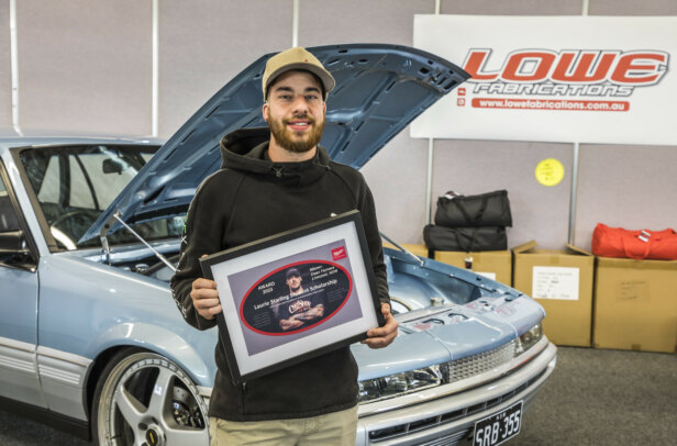
As someone who designs chassis and suspension systems through his Scratch Built Co business, Melbourne’s Chad Forward took the leap into 3D scanning when he realised how much more efficient it could make his work.
“I was at Big L’s Chop Shop for 10 hours trying to work out reference points to plot out a custom chassis, which then took another 10 hours to draw in the computer software. But I was able to scan a pair of super-rare cylinder heads and block of an engine in two hours,” the former Holden Design Centre employee says. “Then there was about four hours of output data to give the clients sufficient data to recast the external measurements of the block.”
While the convenience of a 3D scanner is awesome, it does come at a price. However, Chad looked past the price tag to the opportunities his scanner provides. “It took me four years to convince myself I needed to spend $4000 on a 3D printer, but it took me 15 minutes to convince myself to buy a $40K scanner,” he laughs. “This technology isn’t going to save you money, but it is going to save you time. A lot of what I do is creating things that don’t exist, but scanning saves me having to hand-draw and then replicate it in software, or make a pattern.
“I have a customer who was doing restorations with six of the same cars queued up, so I asked him what the most difficult part of that car was to restore,” Chad continues. “He pointed out the lower edge of a door return, which nobody repros. I scanned one car and 3D-printed a buck that was 1.2mm undersized so that he could beat on it.”
Chad does recognise there are limitations to what a scanner can pick up, and it also takes a talented operator to know how to treat the resulting file so it can be best used later on. “The model of the block I scanned didn’t include any data of the bores, because I couldn’t get the scanner in there to capture that data,” he says. “It does take some experience to know how to output the data, whether it be 3D printing, sheet-metal work or laser-cut, in order to make the products. The unit captures raw data and I can make perfectly smoothed-out, beautifully finished parts, although restoration guys have asked me to make sure the production imperfections are there so they absolutely match the original part.”
Read through the steps below as Chad takes us through the process of scanning parts for a custom 1957 International Metro van project he’s working on.
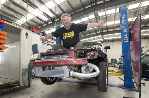
VAN DAMN!
WHILE 3D scanning can speed up parts of the car-building process, there aren’t many shortcuts to take when hand-building a Hellcatpowered ’57 International Metro, and Chad points to teamwork being the key to a killer outcome. “The owner spent two years collaborating with project manager Luke Williams on the design, and his confidence in this quite different process we’re using to build his dream car has been unwavering,” he says. “It is a long build, but we’ll save him a lot of money over the whole build thanks to these techniques, which are commonly used by car manufacturers.”
With the rolling chassis completed, it can then be dyno-tested to ensure all the electronics function before work turns to the body. “After Luke did some preliminary sketches, he cut-and-shut the body to get the proportions bang-on so the exterior sheet metal could be scanned and modelled,” Chad explains.
Modelling the exterior body is regarded as A-class surface modelling, while the bonnet closures, door returns and the like are considered B-class surfaces. “A former colleague from the Holden Design Studio called Nigel Remedios uses Autodesk Alias software,” Chad says. “Nigel started surface-modelling the body, and as a team we’ve designed more aero into the front and (to add rear stability) more rear downforce, due to the 707hp Hellcat drivetrain.”
While the tinware was being modified, the team took the opportunity to refine some of the more agricultural original parts of the vintage bodywork.
“We didn’t like the way the side door would slide, so we also tightened up the mechanism and made it a flush closure,” Chad says. “Because the owner wants to use the van as a van, the tailgate will split, where you can either open the hatch or open the window part.”
STEP-BY-STEP
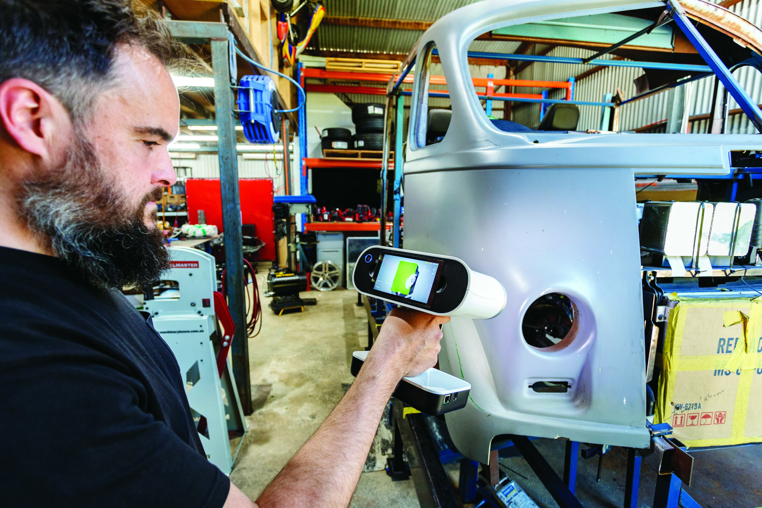
Step 1. Chad uses an Artec Leo scanner, which was reportedly the first one sold in Australia. “I could have spent $20K on a scanner connected to a $20K laptop, but I didn’t want to lug all that around, so I went for a $40K scanner that captures all the data directly into the scanner itself,” he says
Step 2. Chad is scanning a custom 1957 International Metro van in order to tie the Hellcat drivetrain and suspension cradles into a custom chassis and have it all integrated like it was built that way by the factory. He also scanned the body to tidy up the design of door reveals, window fitment and other styling touches
Step 3. The process of scanning an object begins with assessing it, and, if need be, placing datum points (small round stickers) on areas the scanner might have difficulty reading clearly. Chad’s scanner reads at such a high resolution it doesn’t require datum points, so he is able to skip this step
Step 4. Having scanned the Metro van body, the United Speed Shop Magnum IFS and the modified Hellcat rear suspension cradle, Chad designed chassis members to tie it all together, which project manager Luke Williams then jigged and TIGwelded. Chad is now doing scans of the steering column so he can make an integrated mount for it, as well as all the other under-dash accessories
Step 5. As the scanner creates a three-dimensional model, the object needs to be turned over to see every face, as well as the inside if that is also part of the piece. This means you’ll need plenty of space around it and have worked out a way to see every side
Step 6. The resolution of scanners has improved over time, drastically cutting scanning time. The higher the resolution a scanner can read, the more information it picks up off the surface of the object and the better quality model it creates
Step 7. Ensuring you have a high-quality scan file is paramount to getting a good finished product. “The scanner captures a ludicrous amount of data, and, just like with digital photography, the time spent post-processing your scan directly correlates to the quality of your model,” Chad says
Step 8. f the model made by the scan is a ‘point cloud’ or ‘polygon mesh’ file, this will need to be converted into a different file type so the CAD program can see the model properly. “Understanding what to do with the scan once you have it in the software is a key to getting the most out of 3D scanning,” Chad explains
Step 9. The right modelling software is just as important as the scanner itself. “I use Artec Studio software, and I can 3D-print straight out of the scanner, though there are limitations,” Chad explains. “The scan is essentially a 3D picture, so if I scan a stapler and 3D-print that, it won’t just print a working stapler. You’d need to scan all the individual mechanical parts and work out how to fit them all up”
Step 10. Now the model has been exported into engineering software like SolidWorks or Fusion 360, it can be broken down into individual parts. By scanning an empty engine bay as well as the engine you want to fit to it, the resulting 3D models can then be used to digitally test-fit the combo long before you get an engine crane, grinder or MIG welder out!
Comments