Bolting a couple of turbochargers onto the all-alloy Chev is a good power-adder no matter which way you look at it.
This article was first published in the June 2011 issue of Street Machine
The owner of this white VX Commodore certainly understands the advantages of going this way. Already wearing a Gen TT entry-level kit and a Queensland compliance plate to suit, it was an easy decision to purchase the hot streeter.
But as always, the new owner wanted more. A closer inspection of the well-travelled kit revealed numerous installation issues — surprisingly it hadn’t become what’s known in the industry as a bonnet-burner. The poor installation, combined with the fact that the engine had begun blowing a bit of smoke prompted the owner to embark on a full engine build and a more serious twin-turbo installation. The work was entrusted to Ultra Tune in Dandenong.
Normally we’d agree that this work seems a bit out of character for Ultra Tune but some of the staff at this branch are serious performance enthusiasts. That’s normal for Dandenong — many of the toughest and fastest cars in the country have emerged from the area’s numerous workshops. Time to throw out the old and bring in the new!
SOLID FOUNDATION
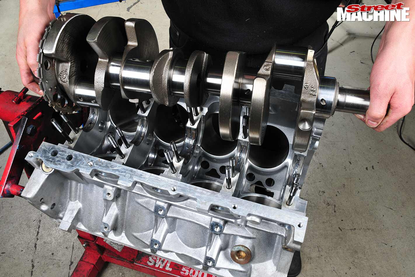
THE original engine had pretty severe wear and glazed bores. To create a bulletproof foundation, the standard crank was reground and fitted with Manley H-beam rods and forged Mahle pistons, along with studded mains and cylinder heads. The heads were ported and outfitted with higher-rated conical single springs and titanium retainers, all operated by a VCM Suite forced induction cam (0.596in lift, 233 duration, 114deg lobe centre).
As with the factory oil pump, the replacement pump (above) had to be relieved on the back to clear the double-row timing chain. Extreme care is needed when doing this as the housing at the crucial point isn’t very thick.
Under major braking, acceleration or cornering, the oil pick-ups on early LS1s can become uncovered. To prevent this, the factory fitted a more elaborate baffle (above) from VY models onwards. While the sumps are interchangeable, the original had already been modified for the oil returns and the later model’s sump was damaged, so the baffle assembly was swapped.
This took a bit of modification but a new sump lists at about $1200, so it was worth the trouble.
CORRECTING THE INSTALLATION:
STEP 1.
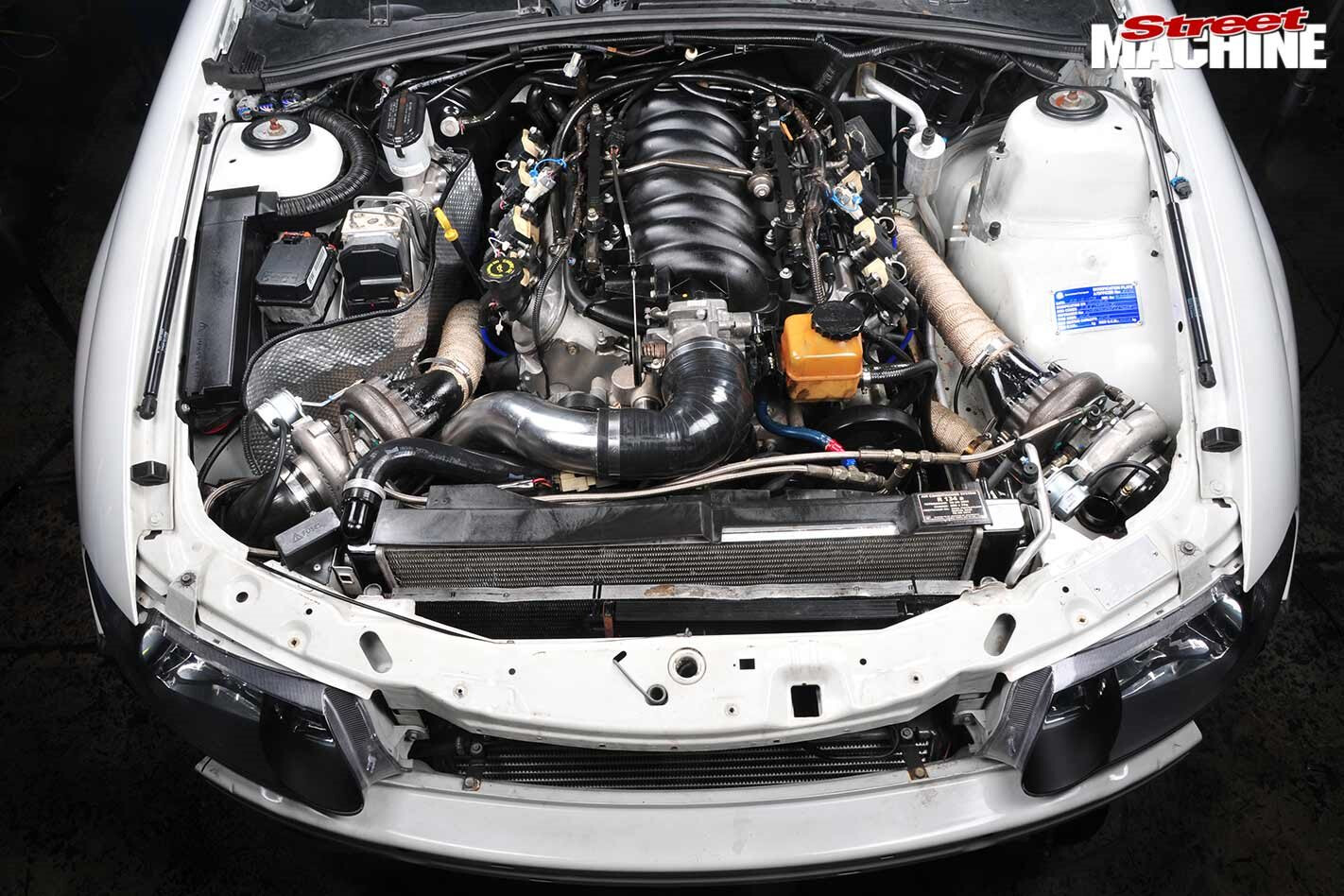
When the car arrived it was found to be making just 325kW at the wheels — no wonder the owner was searching for more grunt. Although it was an entry-level system, the basic kit wasn’t too bad. However, the actual installation was one of the worst we’ve seen, with cable ties and electrical tape holding some parts together and plain household cooking foil used for heat insulation in some places.
STEP 2.
First job — remove the old system. Note how the factory manifolds are reversed so that the outlets point forwards. A feed pipe connects each manifold to one of the turbocharger turbine inlets as shown.
This method certainly creates a tight fit for the turbo exhaust pipes but it does bring the compressor outlets closer to the intercooler, which makes for shorter pipe-work between the two
STEP 3.
The original kit used Chinese KKR bushed turbos that didn’t make boost until 2800rpm and ran out of it by 5000rpm. Basically, as soon as it got to 10psi the highly restrictive wastegate opened and power rapidly died. The backing plate prevented the gate from opening properly and when it did, it directed the secondary stream across the main exhaust flow. New units are Garret GT 28/17R ball-bearing types.
STEP 4.
Fitting custom pipe-work is straightforward yet tricky. On the one hand it’s simply a matter of getting a bit of pipe, holding it pretty much where it’s supposed to go, making an estimate of where it should be cut and then cutting it. These days everyone buys mandrel bends and cuts them to size. A stainless steel bend of this size (generally available at your local exhaust shop) costs about $50.
STEP 5.
Tube can be cut in a number of ways; one of the best is with a chain-type pipe cutter. This type of cutter readily adjusts to any size of pipe, works quite quickly and, most importantly, cuts straight. Cuts made with a hacksaw tend to wander unless you’re really practised at it. Even cut-off wheels can flex a bit under some circumstances, particularly when trimming close to the end of a section in hard material.
STEP 6.
Adam does most of the performance work in the workshop and he has good gas welding skills. Although he welds things together with TIG, he regularly uses oxy to modify sections of piping.
Here, he’s applying heat to form clearance reliefs for the flange bolts. On a bend like this, Adam says he finds it easier to get the orientation of the bend correct and then form a merged flow path for the wastegate gases.
STEP 7.
The original dump pipes were two-inch, however more flow is needed for the larger turbos, which is why these 21/2in units are being constructed. Once the basic sections have been cut, they’re tacked together to check that everything is heading in the right direction before final welding. The job can be done with a MIG but TIG is everyone’s tool of choice these days. Oxyacetylene welding can also be used.
STEP 8.
Increasing the dump pipe diameter made everything tight down the side of the engine. The bend out of the turbocharger on the driver’s side ended up a touch wide and brought the extension into contact with the factory manifold. The bend was heated with the oxy and then the entire duct was bent away by a couple of millimetres — try doing that without heat! You can see the heat mark on the bend.
STEP 9.
The turbine exhaust pipe on the driver’s side had to be flattened a little (arrow) to get down between the factory exhaust manifold and the new heat shielding. Slight flattening of a pipe doesn’t hurt flow that much. This shot shows how these kits use the factory cast manifold to gather up the exhaust streams for the turbochargers. The ports in the cylinder heads have been opened up considerably to increase flow.
STEP 10.
These particular turbos were chosen as they use the same T25 flange plate as the original KKRs, allowing the feeder pipes to be reused. Also, their 450hp capability is easily enough for the job and, most importantly, they fit.
Bigger GT35R units (capable of 500hp) were considered but wouldn’t fit. Before and after completing each weld, it’s a good idea to clean up the insides of the pipes while you can still reach them.
STEP 11.
Some lines and pipes — such as the oil return line Adam is attaching — can be fitted before dropping the engine in place.
Others, like the turbine exhaust (above) are best wrestled into place with the engine about halfway in, while the rest are installed once the mill is bolted firmly in place on its mounts. Perhaps Max wouldn’t struggle so much if he had GM components tattooed on his forearm instead of Honda ink!
STEP 12.
While turbos are designed to deal with heat, most of the things around them aren’t (like the headlight plug, below) making heat shields hugely important — note the heat wrap in Step 09.
If the engine is removed from the car, it’s best to add heat shielding to all the areas it’s needed (below) before it goes back in.
Much of the area shown was actually covered in ordinary household cooking foil in the original installation!
STEP 13.
It’s hard to be perfect but you need to be close — making bolt holes line up might call for a bit of extra leverage but not too much. Also, you don’t want sealer squeezing into the gas path, so it was applied closer to the outer edges of the flanges, allowing it to ooze outwards rather than inwards, with any excess cleaned off. The original installation had bad exhaust joins that were leaking everywhere.
STEP 14.
The twin inlet, single outlet air-to-air intercooler wasn’t removed during the upgrade — it was one of the best parts of the old set-up; the workmanship and the ducting were absolutely top notch.
Again, the actual fitting let it down but that’s not the manufacturer’s fault. Measuring in at 700 x 300 x 80mm it’s well designed and quite effective at cooling the hot air discharged from the two compressors.
WRAP UP
WE HAD to go to press before the guys had a chance to dyno-tune the new installation. However, the package was designed — and will be tuned — so that below 3000rpm the car will be well-mannered enough for grandma to drive. Above 2900rpm is where the fun starts. The turbos will come on boost and combine nicely with the 3000rpm converter and 2800-6500rpm camshaft, with the ultimate goal being 450kW at the wheels.
Why only 450? Because a genuine 450 to 500kW at the rear is heaps of power for the street, while dependability and driveability took priority over producing a Mount Everest dyno graph. This upgraded package will achieve 450kW with ease and without over-stressing any components.
THANKS to Dandenong Ultra Tune (03 9791 2000) for help putting this yarn together.

Comments