A rear-mounted turbo is a neat, efficient and cost-effective power boost alternative
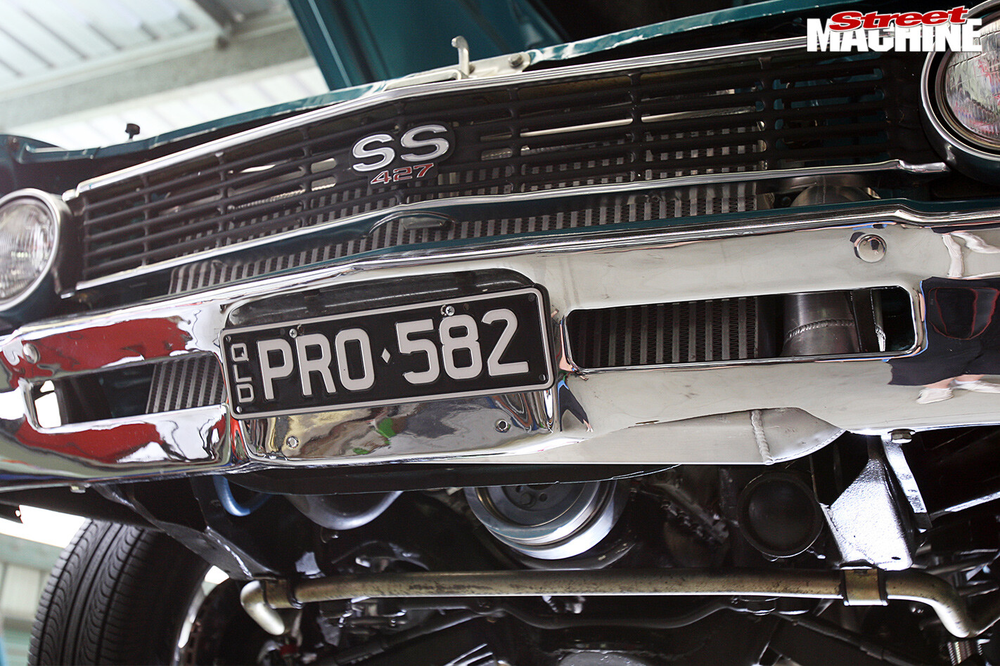
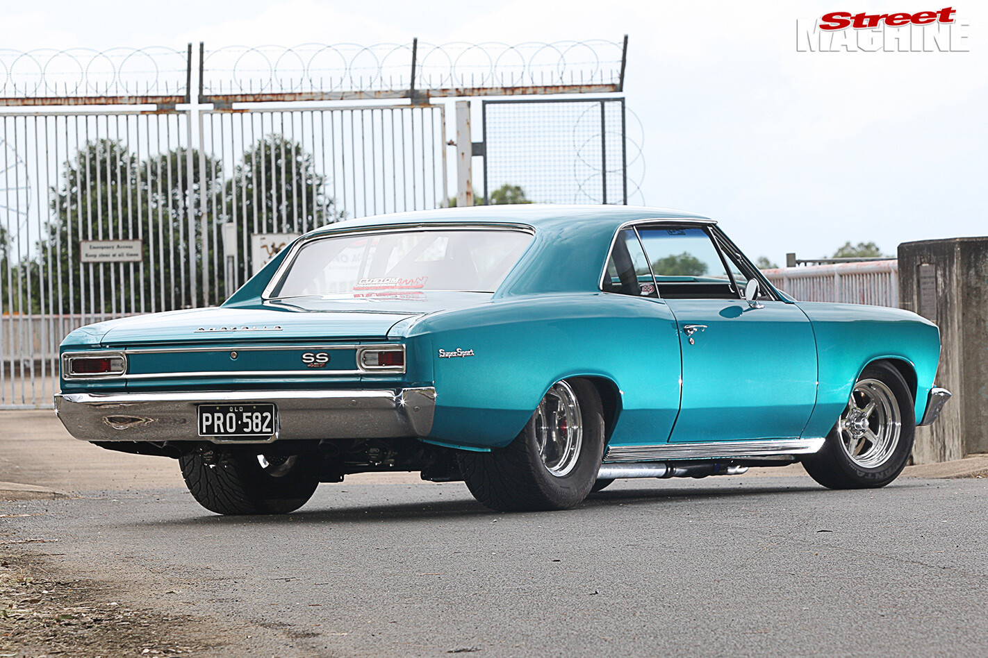
CHRIS Hollingworth wanted to give his 500ci, big-block-powered 1966 Chevelle a healthy kick in the power pants and after considering centrifugal supercharging and possibly nitrous, settled on turbocharging.
Off boost, the Chevelle would retain street driveablity (it sees plenty of street duty), however when the boost kicks in, it’d get the sizable power boost he was looking for.
Typical turbo installations use a pair of scrolls mounted in the engine bay up front, blowing directly into the engine or through a front-mounted air-to-air or water-to-air intercooler. However, Chris wanted to go down a different and surprisingly not uncommon path.
US company, Squires Turbo Systems, (STS) has developed a remote-mount turbo system that positions the scrolls down the back of the vehicle – either in front of, or behind the differential. They offer fully-developed, bolt-on kits for numerous vehicles including Corvette, Dodge Charger, Dodge Challenger, Dodge Ram, Mustang, Camaro, GM SUV, Hummer and Pontiac GTO (Monaro/Commodore). As well as specific-fit kits, they also devise custom, one-off systems for applications such as Chris’s back-halved Chevelle.
Convinced that this effective rear-mounted turbo arrangement was the way to go, it was time to get stuck into the installation.
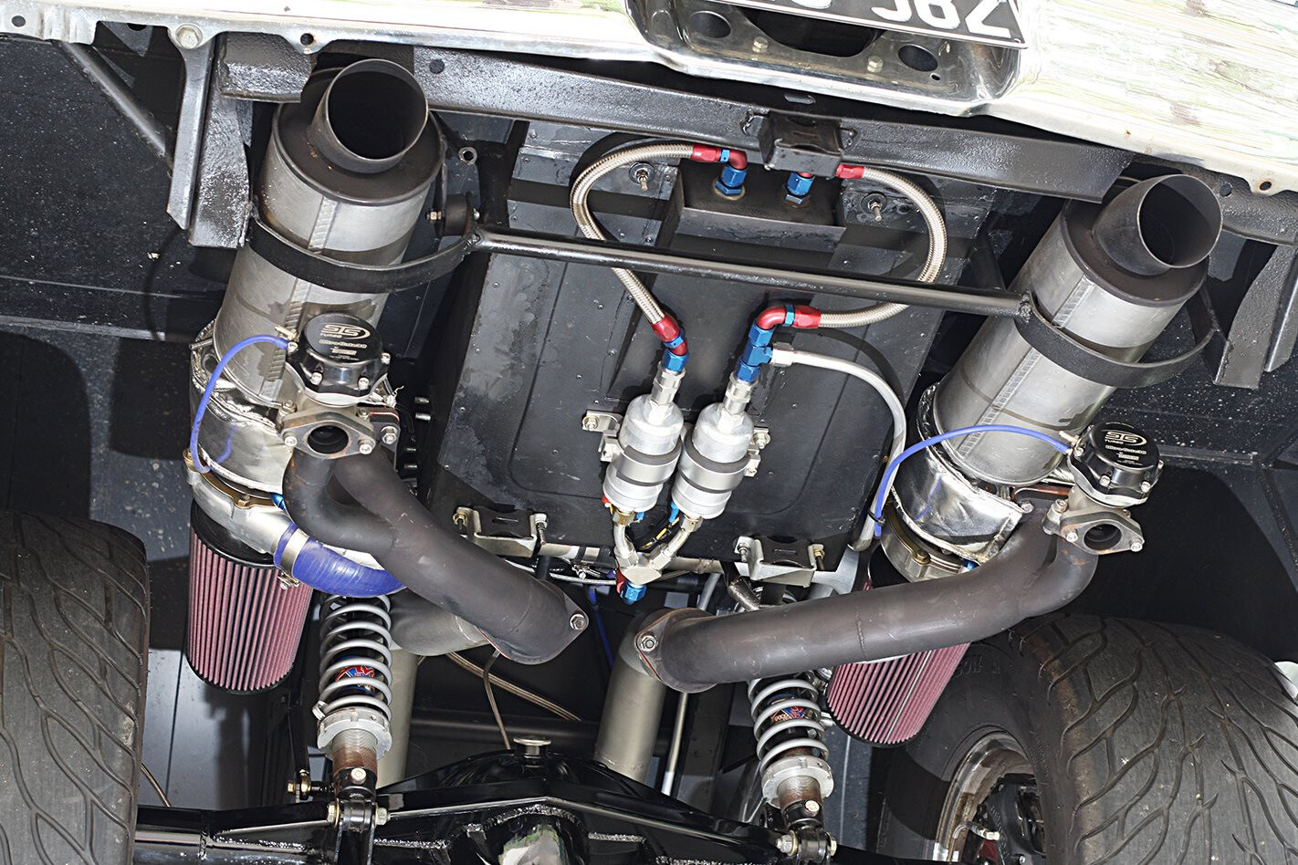
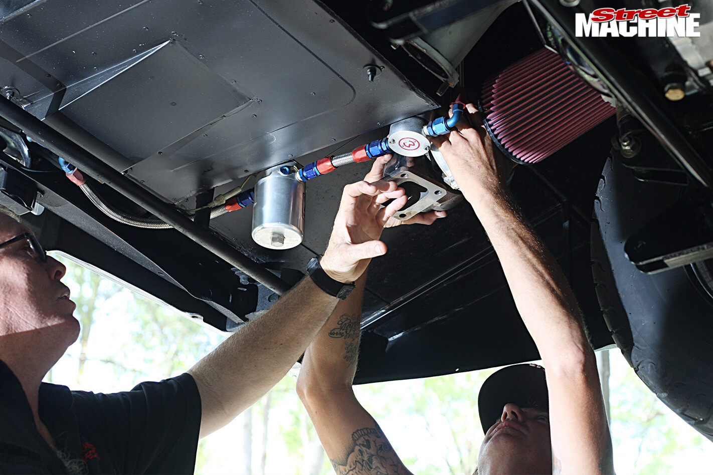
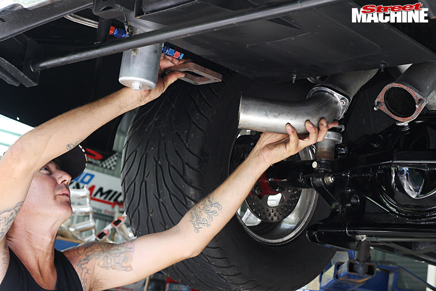
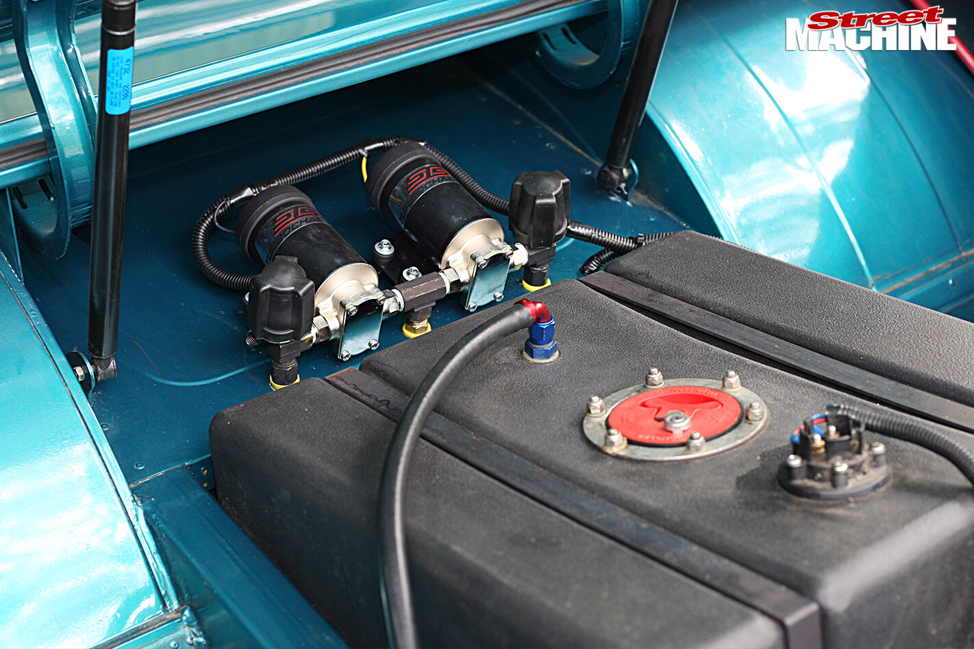
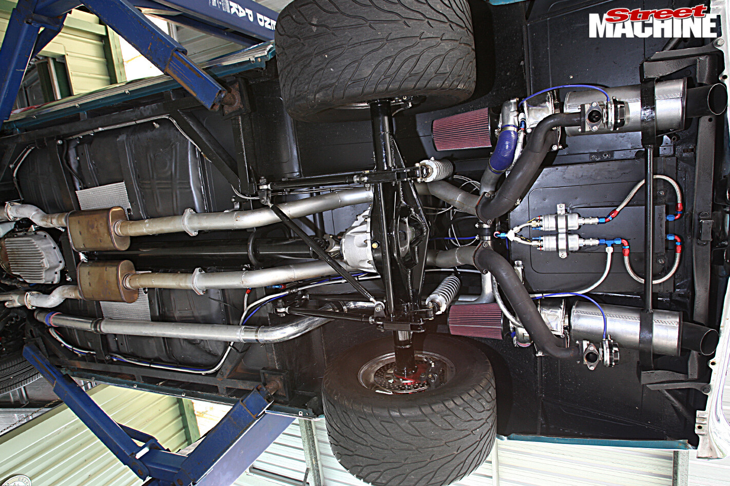
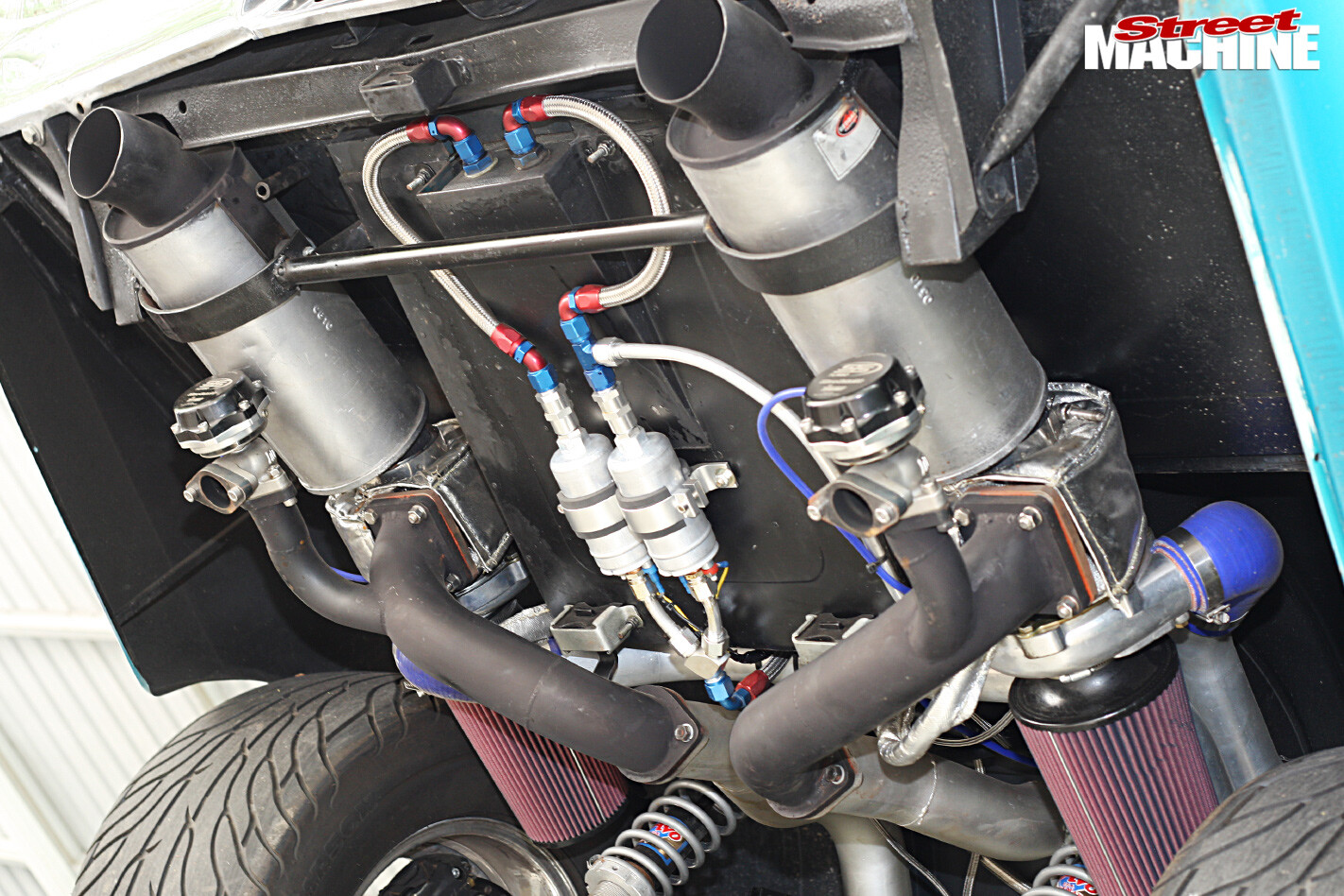
 STEP 1 Being a back-halved car, there’s plenty of room behind the diff to accommodate a pair of sizable turbos. In less accommodating vehicles, STS has found that mounting the turbo(s) in front of the diff or at the very rear also works equally well. The side-mounted fuel pump and filter were removed and replaced by two centrally-mounted Bosch 044s and a Mallory (P/N 4307) high-flow regulator – all good for 1000hp
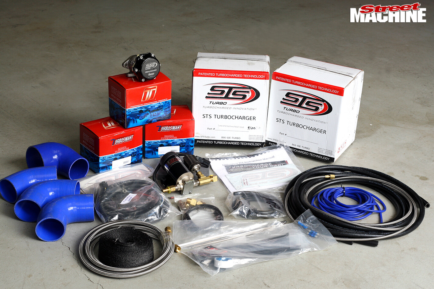 STEP 2 After much discussion with STS regarding the application and installation, they recommended a pair of their 67mm T4 turbos, which are good for around 750hp each. Turbosmart manufactures many ancillaries for STS and supplied the STS-branded wastegates, blow-off valve, silicone hose, oil line and boost reference line. The only thing missing is the actual pipe, which is supplied with specific-fit kits
 STEP 3 Positioning the scrolls is always a complicated packaging exercise. They can face in any direction as long as the exhaust gasses enter up into the turbine housing. Also, the air inlets and the turbos themselves should be kept as high as possible and out of harm’s way, while simultaneously being kept well away from anything that will be heat affected. Note the standard T4 turbo mount
 STEP 4 Chris’s good friend, Les at Fat Pipes (07 3285 7417), was commissioned to build the custom pipework. Compared to fabricating a set of one-off extractors, this is a fairly straightforward undertaking
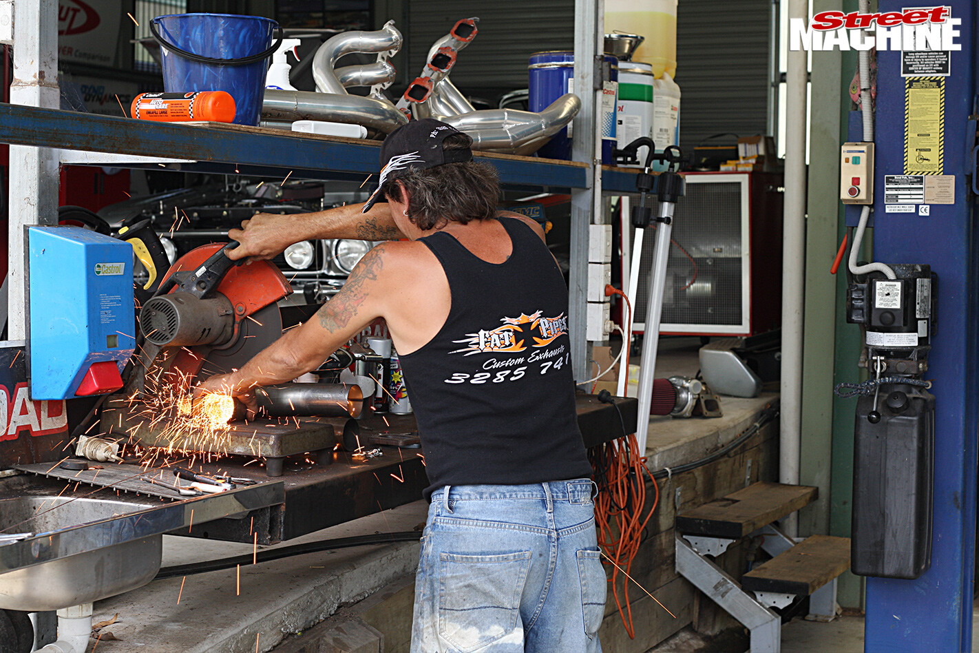 A couple of Les’s fabrication tricks include temporarily hanging the turbos in place using welding wire, along with hand bending other pieces of wire to determine the degree and position of the bends required
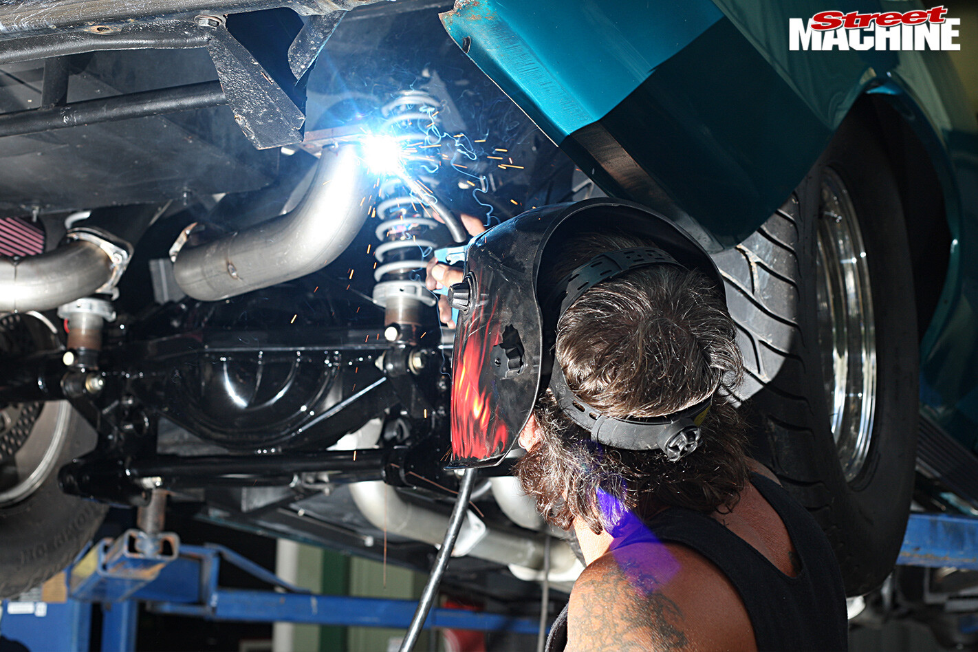 STEP 5 Rather than completely welding each join until the whole job is completed, Les just solidly tacks each section as he goes. That way if a section needs to be removed formodification, it’s much easier to cut a couple of tacks than it is to cut a full weld. Once everything is completed and he’s happy with the fit of all the components, Les will go back and fully MIG/TIG-weld each joint
 STEP 6 Things are beginning to take shape. To get the best flow possible and to ensure there are no repeals (reductions in cross-sectional area) in any of the bends, Fat Pipes used 3.0-inch mandrel bends, which were carefully cut to size. This is a common technique with one-off jobs like this, as it’s exceedingly complex to create compound, mandrel bends from straight sections of tubing
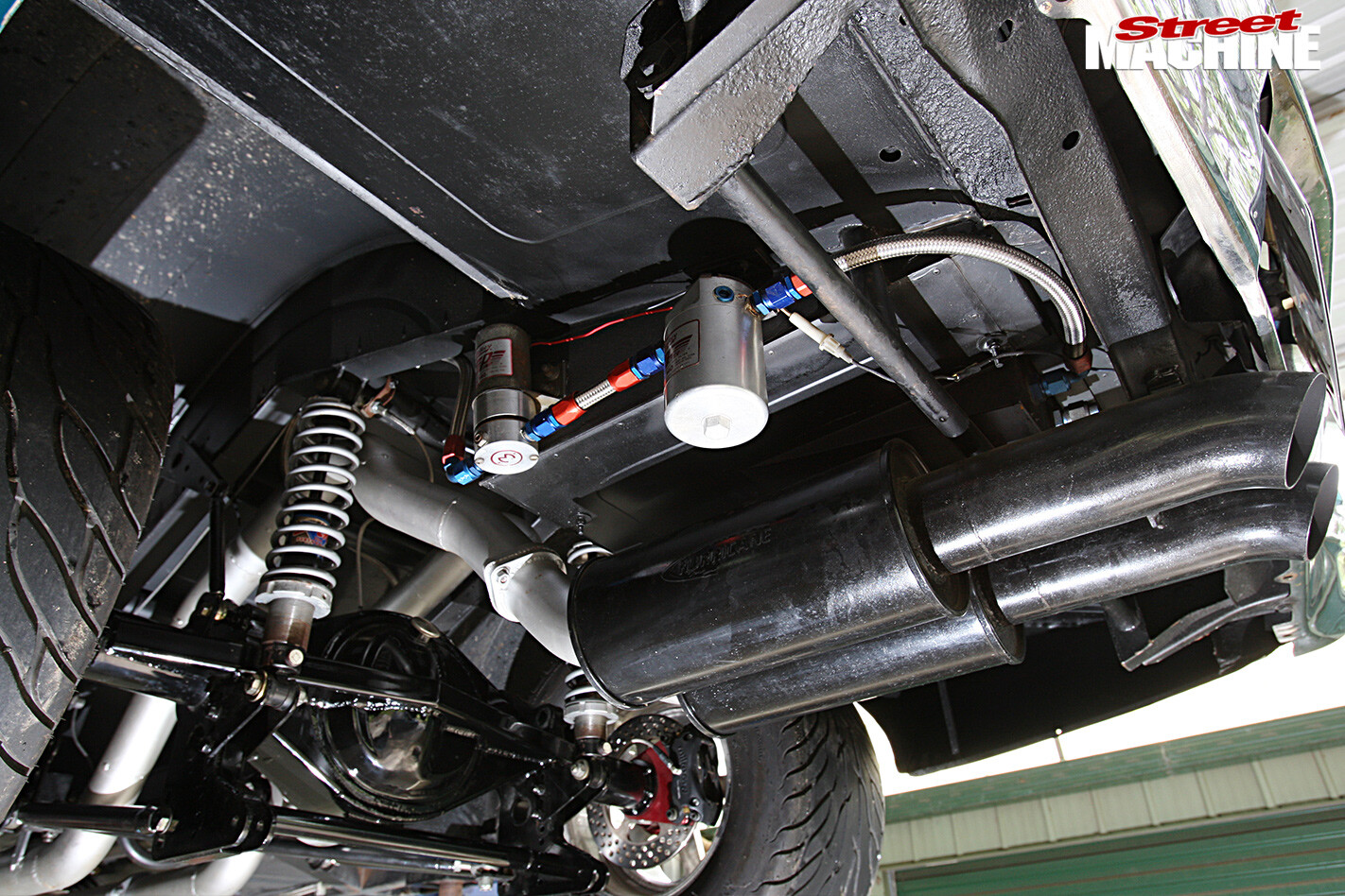
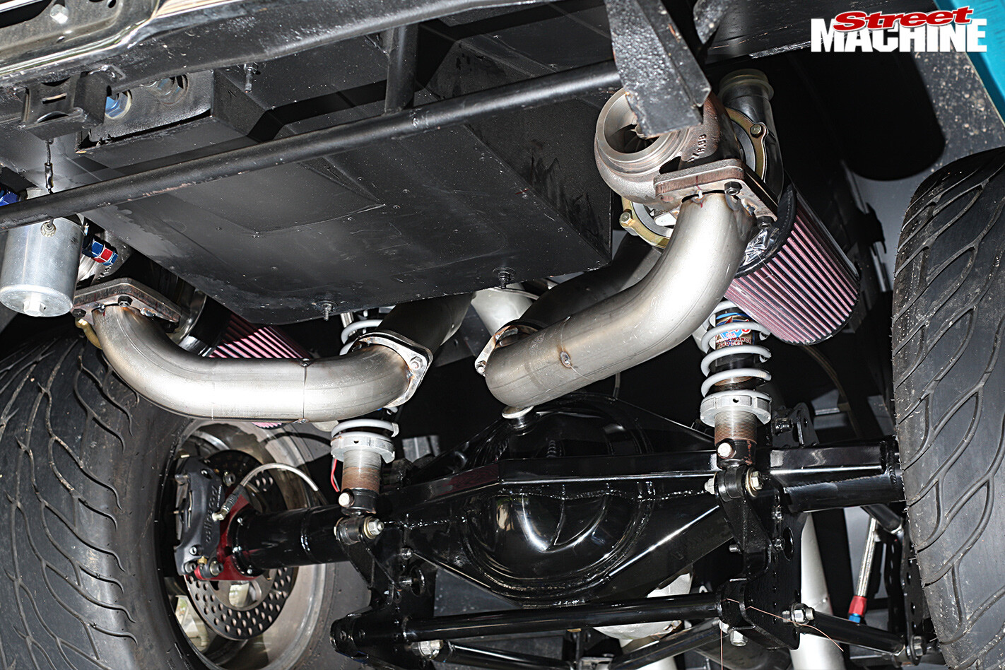
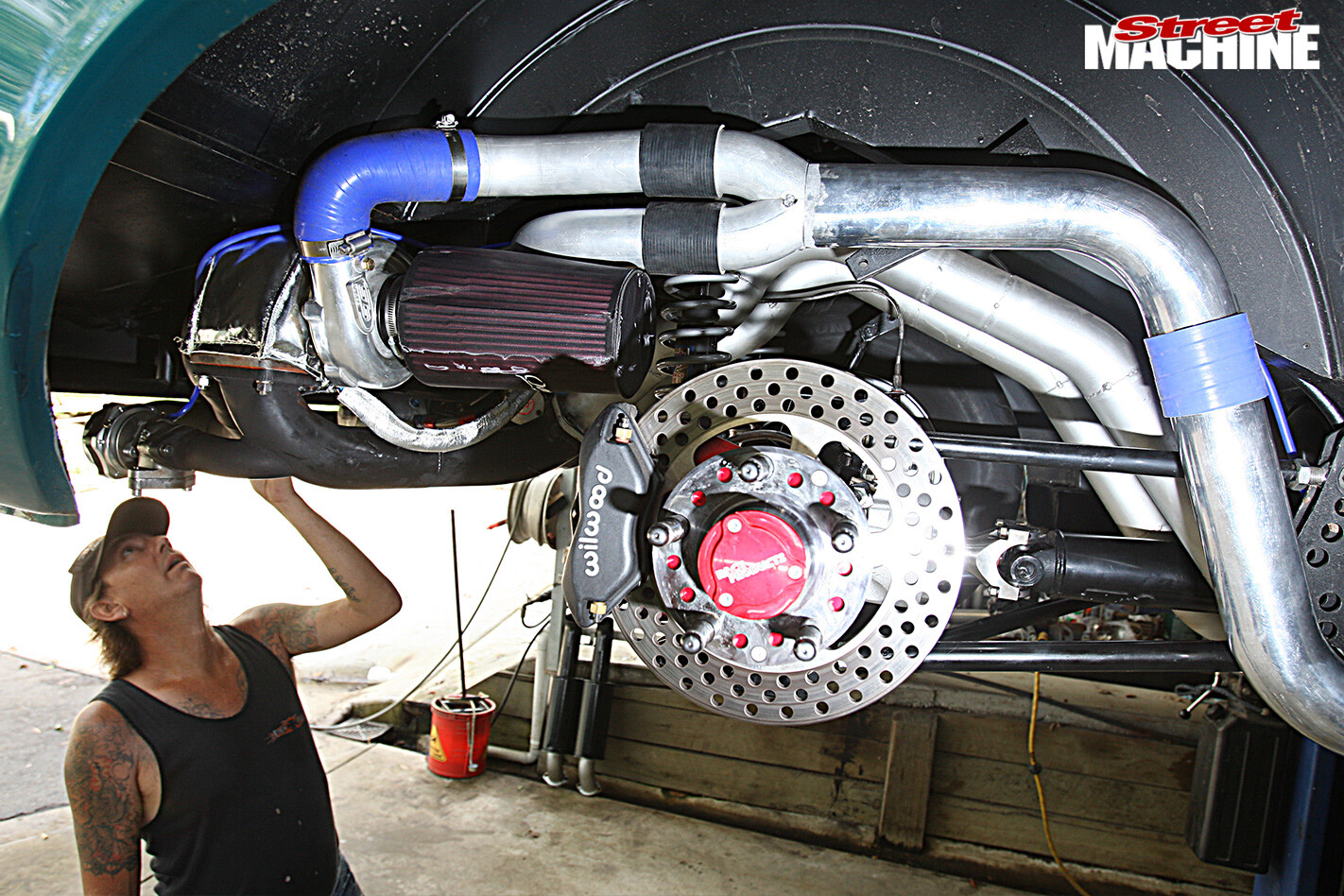
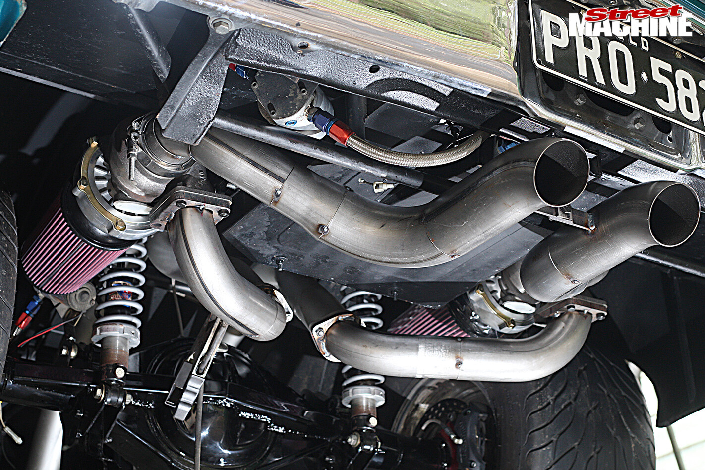 STEP 7 Cutting and welding each section of pipe to form nice flowing symmetrical contours is the most time-consuming part of the job and is an art form in itself. Compare the dump pipes here to the pair of large mufflers in other images. Chris’s street set-up includes mufflers, but if he’s looking to put some numbers on the board at the track, or run amok at his favourite event, Powercruise, he swaps back to these dump pipes
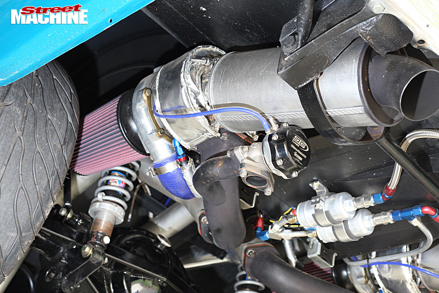
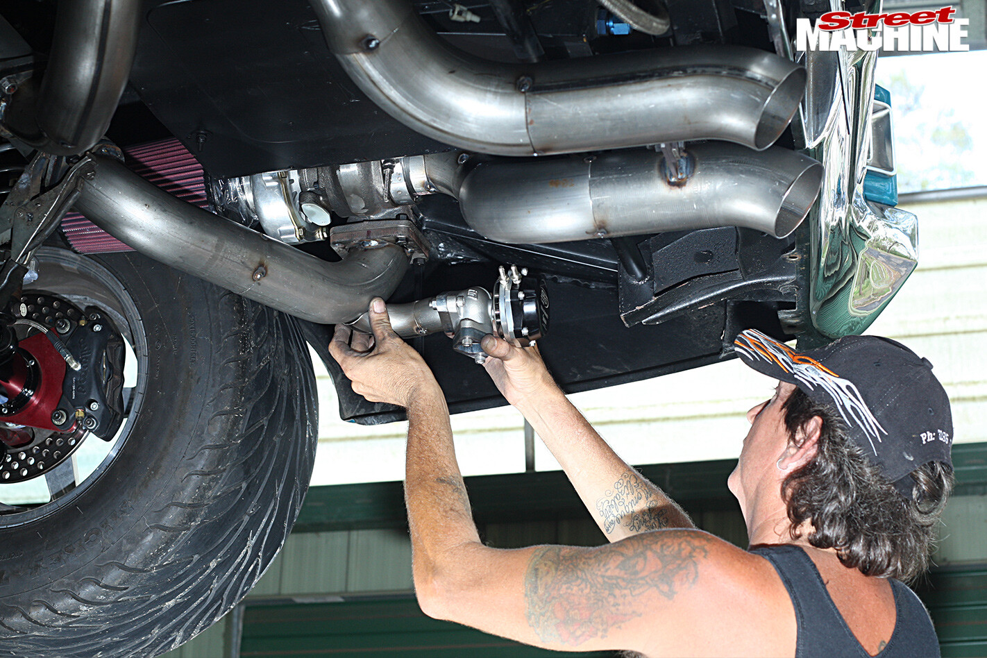 STEP 8 The last part of the rear section to be fabricated is the ducting and mounting flange for the dual 38mm wastegates. STS suggests that the optimum position for the wastegates is in the bend right before the turbo, as this is the point of maximum flow. The wastegates control turbine speed (which in turn controls boost pressure) by bleeding off exhaust pressure to the atmosphere
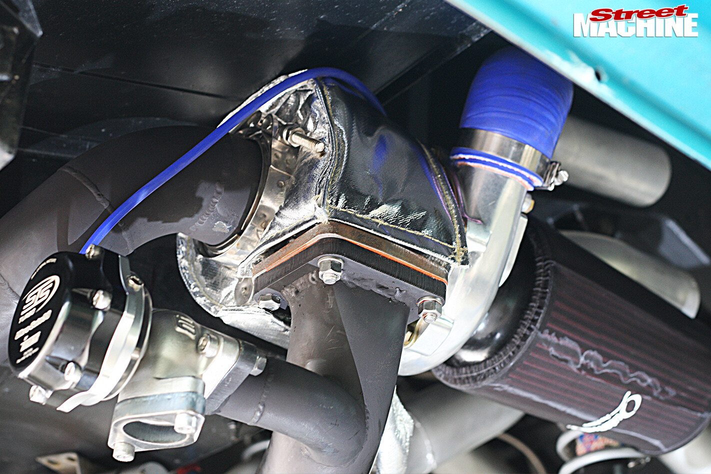 STEP 9 For uninterrupted flow into the wastegate, Les ensured there was no lip pipe-to-pipe. We’ve also jumped well into the future, as all the pipe work has been finish welded and HPC coated in black to help reduce radiated heat. Note the turbo covers to help prevent heating the heck out of the Chevelle’s floor. The wastegates pick up their boost reference (blue line) from the intake manifold for more accurate readings
 STEP 10 Given the position of the turbos, their lubricating oil is unable to drain back into the engine’s sump, as it would in a typical engine bay configuration. Instead this pair of heavy-duty electric scavenge pumps collect the oil and pump it back into the valve covers. Once again the length of the lines help cool the oil while it’s flowing to and fro – negating the need for an external engine oil cooler
 STEP 11 The outlet of each turbo is ducted into a single 3.0in alloy pipe that runs all the way up to the front-mounted intercooler. With the system designed for a maximum of 15psi of boost, there was no need to use elaborate V-clamps on the boosted side of the system
 Mind you, every alloy piping end has been beaded and every flexible joint has silicone hose, all secured by the heavy-duty hose clamps supplied by STS
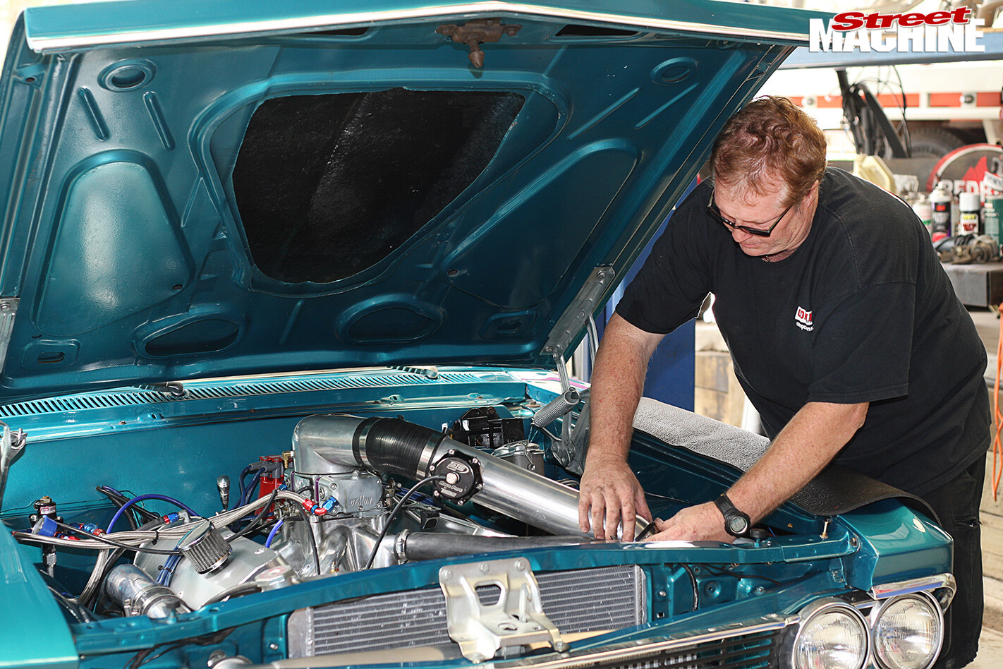
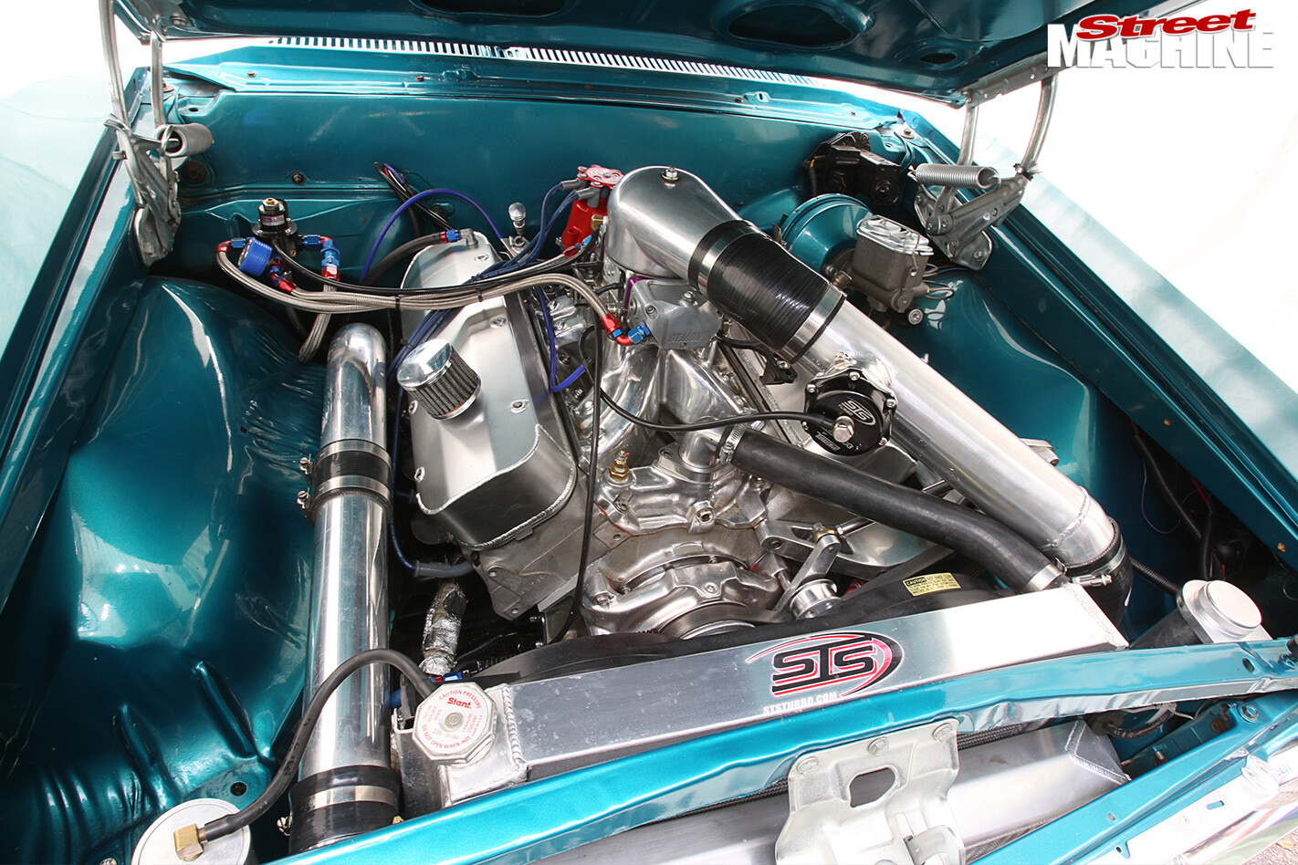 STEP 12 Chris fabricated the intercooler piping in house at Holley Pro Sport, plumbing it up through the engine bay to maintain maximum ground clearance. STS claims the long intake piping acts much like an intercooler, which means systems running 6psi or less generally don’t require a dedicated intercooler. With Chris’s Chevelle capable of running up to 15psi, he felt it was good insurance to incorporate one anyway
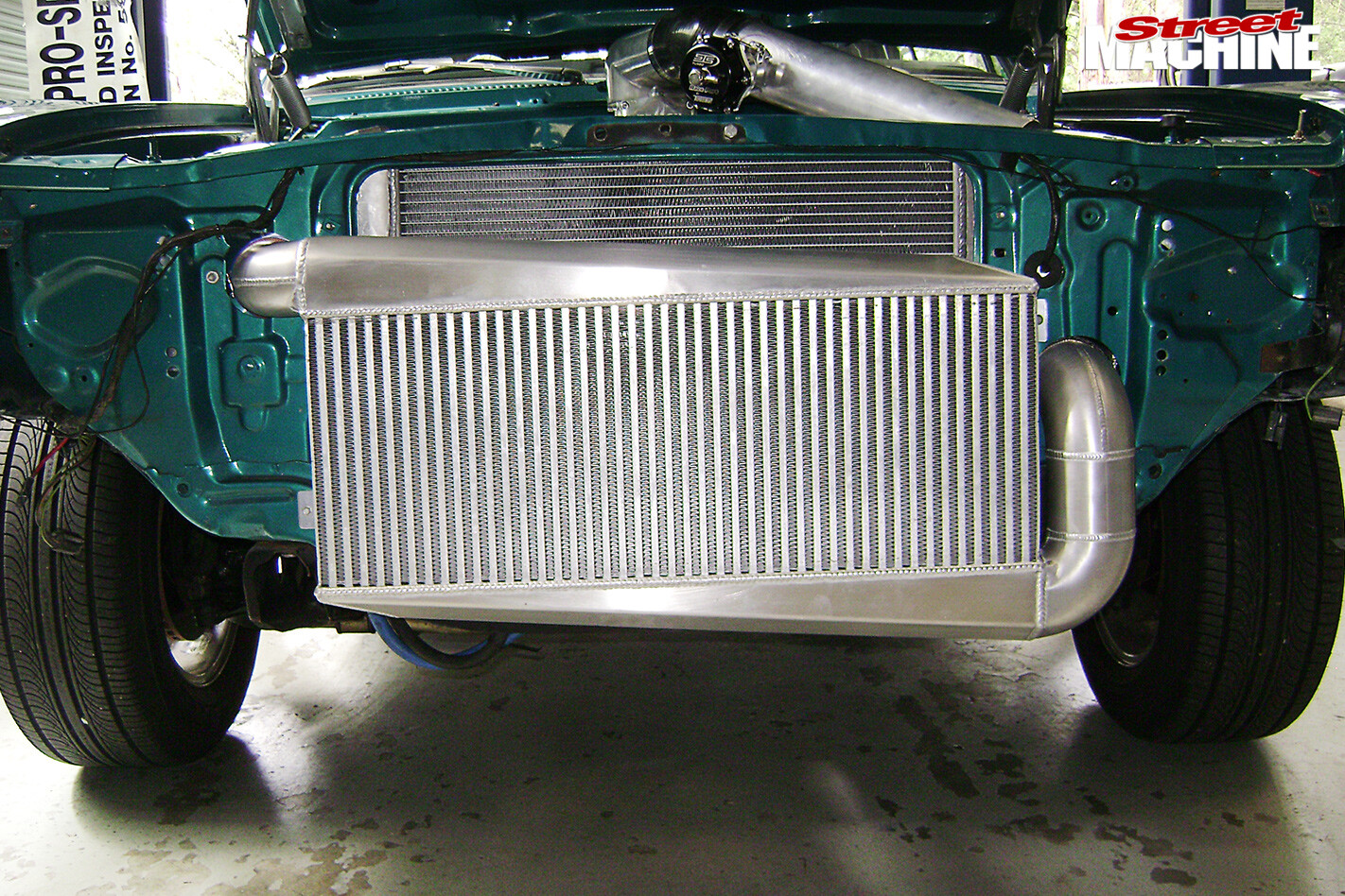 STEP 13 The bumper bar had to be trimmed slightly to fit the high-flow intercooler custom made by ARE (07 3205 4620). The 715mm x 260mm x 73mm core features a 3.0in inlet and 3.5in outlet piping
 The top and bottom tank’s wedge shape and internal diversion plates even out airflow through the entire core, maximising effectiveness. The cooler will support up to 1500hp, which is perfect for this tough streeter
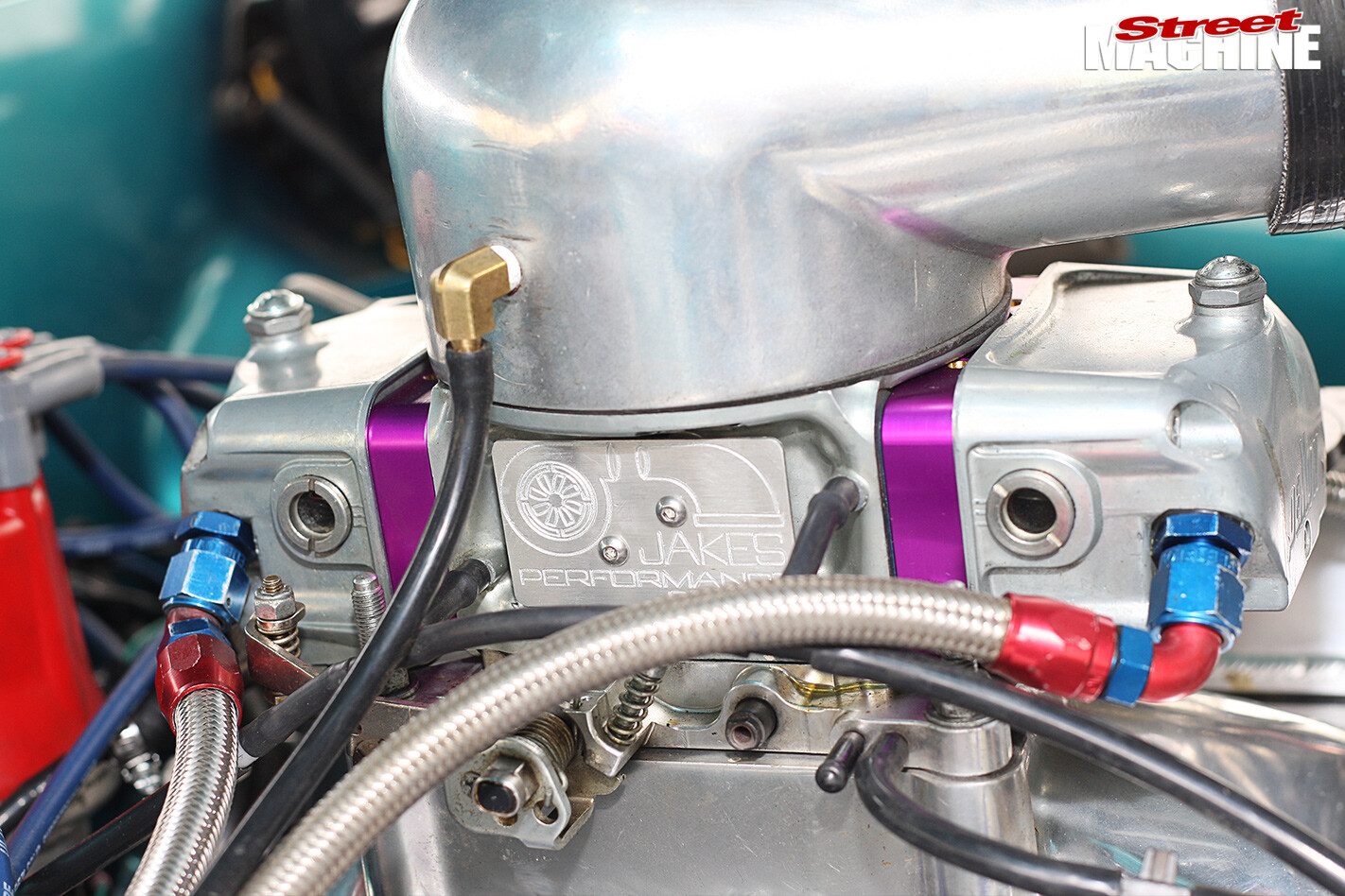 STEP 14 Chris’s 850 Demon was modified by Jakes Performance (02 6255 4545), who are blow-through carburettor specialists. While able to build carburettors capable of handling 35lbs of boost, Chris’s Demon is much simpler
 It runs their titanium needle and seat, ecalibrated metering blocks and dual-boost-referenced power valves, all working in conjunction with a one-to-one, rising-rate fuel-pressure regulator
WRAP UP
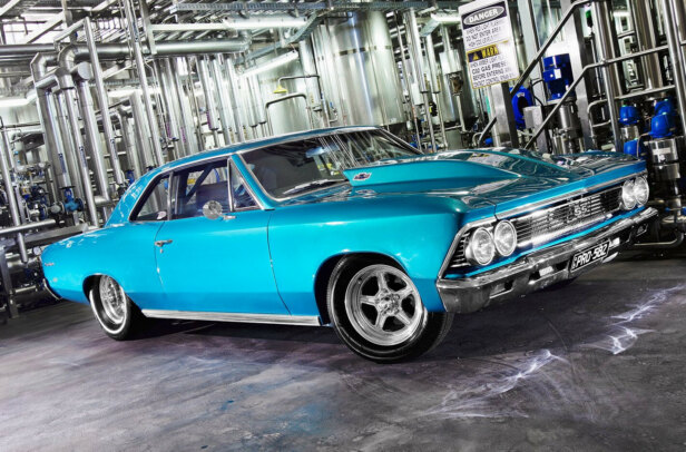
THE Chevelle’s 500-cube big-block Chev had a mere 400hp at the rear tyres before the STS turbo system. With only basic tuning and 5.4psi of boost, the mighty Chevelle spun up over 680rwhp!
 Even better, the indications are that the combo has the potential to make well over 1000hp at 10psi. Chris can’t wait to head to Powercruise where he’ll now have the grunt to skid the whole back straight.
 With simple installation, less heat issues than a comparable underbonnet set-up, highly efficient and plenty of power on tap, STS rear-mounted turbos are worth a closer look.
PRO AND CONS
 STS has been promoting rear-mount turbos for some years in the face of scepticism that suggests putting the snails down back would cause more turbo lag. Here’s the drum, turbo lag is not significantly influenced by turbo position – as shown with the low-mount systems commonly used in VE Commodores. Rather correctly matching the turbo to the engine and the application is the overriding issue in optimising boost response and minimising turbo lag.
Advantages of rear mounting include simpler installation, stealthier appearance, reduced passenger compartment noise, no increase in underbonnet temperates, lower inlet temperatures, better weight distribution and there’s no need for expensive custom headers. Heat is the enemy of all turbos, but here the rear-mounted turbo housings are exposed to cool, flowing ambient air, helping them to run cooler and more effeciently. A typical front-mounted turbo can run as hot as 1100 degrees Celsius, while STS commonly sees temperates of 650 to 700 degrees Celsius with the rear-mounted set-up.
Comments