RIGHTO, so we know what valves do, but what pushes them down?
In most traditional V8s it’s a rocker, which is like a seesaw that’s pushed up at one end by the cam-driven push rod so that it pushes down on the valve at the other. A roller rocker is different to a normal rocker because it has a roller that comes in contact with the end of the valve stem rather than a plain metal tip. While standard on some engines these days, earlier units have the traditional rockers and replacing them with roller rockers is an important step if you’re keen on performance.
As we mentioned, the normal rocker tip is made of pressed steel and as the rocker depresses the valve, this tip moves in a small arc causing it to slide across the end of the valve. This pushes and pulls the valve stem from side to side and causes uneven wear or ‘bell mouthing’ in the ends of the guide. In turn, this bell mouthing leads to uneven wear on the valve seat resulting in poor sealing and loss of performance. The small roller set into the end of a roller rocker reduces this lateral force to largely fix the problem.
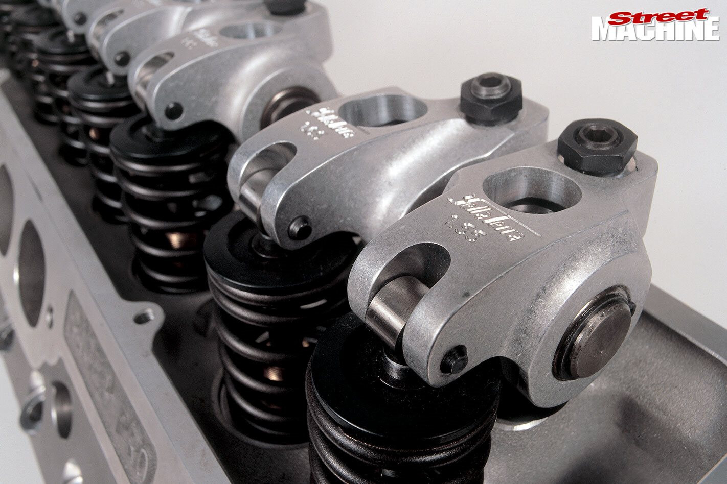
Aluminium rockers are machined out of extruded bars of special material. These Yella Terra units are manufactured here in Australia
For this to be a problem the rockers must be doing a fair bit of work, then.
Well, yes, because, making a car go faster means speeding up the engine’s working components, which subjects all its components to greater stresses. Conditions are worst for reciprocating parts like pistons, conrods, valves, springs and rockers, because whenever a component is made to change direction or speed (or both) it undergoes acceleration. As both the mass and the operating speed of a component increase, changing direction gets harder.
The traditional push rod, or OHV (overhead valve), engine is the worst offender for this kind of punishment. An OHV motor has lifters, push rods and rockers which all add up to considerable weight that must be controlled by the valve-springs. Things get worse in performance application as components are pushed past their original design parameters, so the OHV arrangement needs all the help it can get and roller rockers are a vital part of that help.
Die cast rockers aren’t as strong as those machined from bar stock but they’re less expensive and strong enough for mildly-worked motors. Aside from absolute strength, they still offer all the friction-reducing features outlined
But what exactly are roller rockers an improvement over?
Most traditional iron-block V8 engines came factory fitted with pressed steel rockers and ball pivots (a broken one is shown in the photo below), which are fine for standard applications. However, because standard applications don’t appeal to us much and high-performance applications do, roller rockers are about the only way to go.
Although there are some steel roller rockers still available, most types these days are aluminium which makes them lighter and, strangely enough, stronger. Additionally a roller rocker reduces friction, not only on the valve stem, but at the pivot, too. Rather than pivoting on a large ball like the old ones, roller rockers pivot on needle roller fulcrum bearings mounted on either side of a trunnion that passes through the centre of the arm.
Pressed steel rockers obviously don’t hold up very well in high-performance operation. However, failure can even occur in extremely high-quality units. The blue one here is from Jesel and these are acknowledged as one of the best available in the world
Yella Terra founder, Dave Bennett, explains that larger fulcrum bearings make the rocker stronger due to the fact that their larger contact area is capable of absorbing more force, and having a larger internal diameter means that the trunnion is stronger.
Er, trunnion?
Yes, you can see them mounted in the middle of the roller rockers in the photos.
This shows the arrangement of the trunnion bearings on the mounting shaft
Got it. So are rockers all one size?
Not exactly. They come in different ratios, rather than sizes, and there’s a good reason which we’ll get to in a sec. Firstly rocker ratio is the length of the long (valve) side of the rocker arm divided by the short side. Common ratios are 1.5:1 to 1.7:1. There’s less movement across the valve tip on higher ratio rockers which means less movement across the valve tip, less wear and more reliability.
But wait, there’s more! First, a higher ratio rocker means that a smaller cam lobe can be used to generate a particular amount of valve lift. This is important in an OHV engine, because there’s not a lot of room for the cam lobes to start with making it difficult to make them bigger (for more lift). Also, a rocker ratio that allows smaller diameter bearing journals is better because the bearing-to-journal operating speed is lower, while the contact length of a smaller cam lobe results in a lower operating speed against the lifter. This all means that a lighter valve spring can be used. Heavy springs sap a huge amount of energy from a performance engine so using every opportunity to lighten their load is important.
Rockers vary in quality. The Crane version in front enjoys an extremely good reputation world-wide and the Lunati and Scorpion units also hold up equally well. The black one, however, was found to be made from the same aluminium as that used in windows
How do I fit them to my old Windsor?
There are two basic ways in which roller rockers can be mounted. The oldest had individual studs while newer types pivot on rigid shafts. Either way, fitting roller rockers to an OE head generally calls for the mounting pedestals to be machined flat and to the right height to get your rocker geometry right. Of course, aftermarket heads come ready for rollers.
When using individual studs to mount rockers the stud can flex. Shaft mounting them, or fitting a girdle that links all of the studs together by clamping on to the central adjustment nuts solve the problem. The girdle system works on the principle that not all the valves are open at the same time, so the unstressed studs of valves that are closed can be used to reinforce the stressed studs of any valves that are open. However, if the studs are not perfectly aligned they can be stressed when clamped, which could cause breakage.
Older style stud-mounted adjustable rockers also suffer instability because they float and aren’t firmly fixed down onto the studs. They’re held in place between the valve, pushrod and adjusting/locking nut. In an engine with hydraulic lifters this is not so bad because the lifters keep things reasonably firm, but a performance cam with solid lifters needs some clearance and the whole assembly becomes a bit loose. Although girdles reduce flexure of the studs, they don’t stop adjustable rockers from rattling about. Of course, many successful engines are built with solid cams and adjustable, stud-mounted rockers like this but it’s not necessarily the best method.
Mounting rockers on shafts is generally the most rigid way of supporting them. Some systems have all the rockers on the one shaft, but the current thinking is that pairs of rockers on shorter shafts provides the greatest rigidity. This inexpensive system is used in most high-performance engines. However, they’re not suitable for all valve configurations. Rockers for canted valves still have to be mounted on individual studs because none of the valves (and therefore pivot points) line up.
Note the provision for the largest diameter springs
Is it just pushrod engines that have roller rockers?
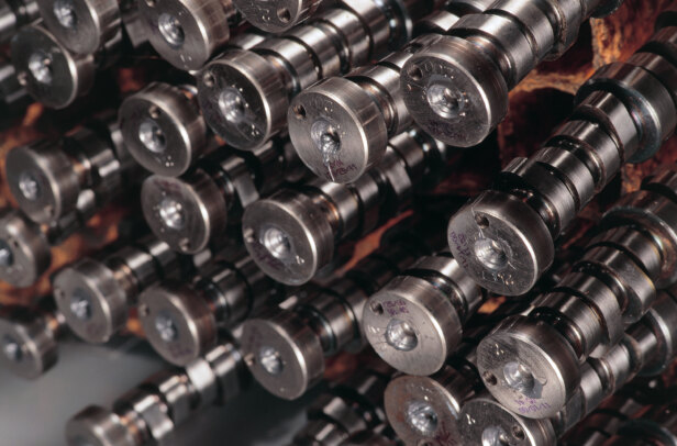
No, in fact motor’s like Nissan’s VH45DE V8 (shown below) might be of modern quad-cam design, but the lobes still operate directly on small roller rockers. These are needed because they can’t work directly on valve tips due to the side forces involved.
The system shown in photo 16 reduces drag across the tip as described previously and reduces friction at the lobe contact points by means of rollers. They’re extremely small and light, so high revs don’t create problems for this engine. Mounting them on hydraulic fulcrums inboard of the cams compensates for wear in service. This raises the matter of differences between hydraulic and solid lifters, a topic we’ll cover shortly!
1. Roller rockers on a quad cam Nissan V8.
2. Yella Terra tested many designs to destruction. The company says that the breakage should occur where there’s least metal, as seen in the arm on the right. If it breaks where there’s more metal, there’s something wrong with the design.
3.Two rockers on a single shaft is the most rigid method of mounting them.
4. Unfortunately, canted valves preclude the use of shaft-mounted rockers. The situation can be helped by using a system with the broadest base possible. This self-aligning mounting system invented by Yella Terra is becoming increasingly popular in the US.
5. It’s easy to see how the shaft-mounted pair at left are more rigid than the stud-mounted versions at right.
6. Shaft-mounting permits the fulcrums to be set back from the factory-defined mounting points. This allows bigger springs and improved pushrod geometry. This can also be done on a stud-mounted rocker by off-setting the hole as shown, although the problem of flexing is still present.
7. Although popular, stud girdles aren’t seen as the cure-all they once were.
8. Bigger diameter bearings allow bigger, stronger trunnions. Also, wider bearings like the one on the left should be used wherever possible. In some head designs, the pushrods are moved a considerable distance from their ideal positions to achieve the best breathing port possible. This results in side-loading through the arm and in these cases, caged bearings like the one second from left are used.
9. Stud-mounted rockers require the machining of rocker mounting pedestals. These interesting Cleveland heads were prepared by Sircar.
10. This Sircar Cleveland uses traditional stud-mounted rockers. In this application, they’ll be fine but it’s important to adjust them properly.
11. (Above and below) The circlip set into the relief on the side ensures that the tip roller doesn’t move laterally. The sequence shows how far the roller moves across the valve tip and the wear it causes
Comments