Here’s how we updated the fuel system in our HQ giveaway car to give it more grunt
WHEN it comes to modifying classic muscle cars, everyone is keen to bolt more horsepower up front, but many often forget about the need to get more ‘go juice’ through to fuel the beast. Most 60s and 70s cars come with a small 5/16in fuel line, and it’s important to remember that the narrowest point in the fuel system dictates how much fuel it can flow. Start pushing the power north of 300 horses and that factory fuel line isn’t going to be doing you any favours.
With our HQ GTS tribute giveaway car, for example, we upped the power to around 420-430hp, and at those levels the 5/16in line just isn’t big enough, especially when you throw half-a-dozen 90-degree bends into the equation.
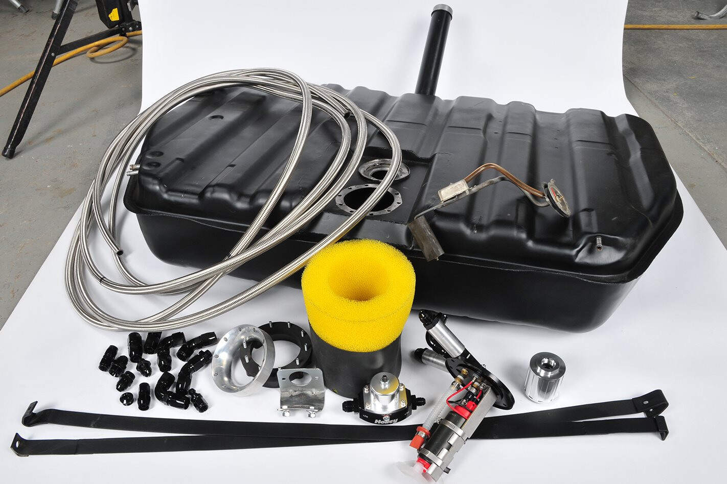
 So here’s how Gary O’Brien and the team at Bendigo Retro Muscle Cars modified the fuel system to meet the new demand. Rather than stick with the original line and mechanical fuel pump, they went for an electrical pump mounted inside the tank, which has also been enlarged to 105 litres for more fuel capacity.
For this job they’ve chosen the Aeromotive 340 Stealth (PN-11142) electric pump with a built-in baffle system. It can work in both carby and EFI applications and can deliver between 284 and 408 litres per hour, depending on the pressure required. That would be good enough for over 1000hp in our application with the right fuel lines, which the boys have also installed. It’ll also be able to maintain a healthy supply around corners at decent speeds. The best part is they’ve retained an authentic-looking appearance from the back end. Winning!
You don’t have to enlarge your tank to use this set-up, as the Aeromotive Stealth pump can be fitted to just about any tank. As with any fuel tank modifications though, it should be done by professionals. Don’t blow yourself up!
STEP 1
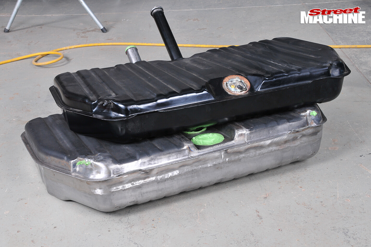
Some people weld a drop section into the factory tank, but this doesn’t look very good in a factory-style muscle car; it’s also vulnerable to hits during road use. The guys elected to add extra capacity to the HQ tanks by splitting the original tank and welding a flanged spacer strip in between the two halves
STEP 2
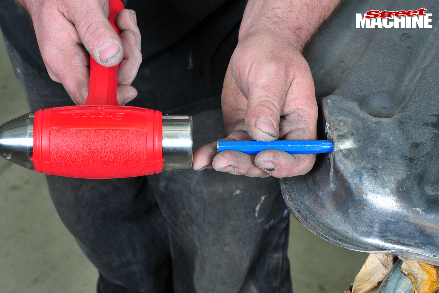
The tank halves had been already been separated and the original breathers removed when we arrived. Gary reckons the factory breather tubes are too small, so while the tank is apart they’ll replace them with 5/16 versions. Rhys, one of the skilled fabricators at BRMC, enlarges the original holes in the tank upper section with a round, tapered-tip punch
STEP 3
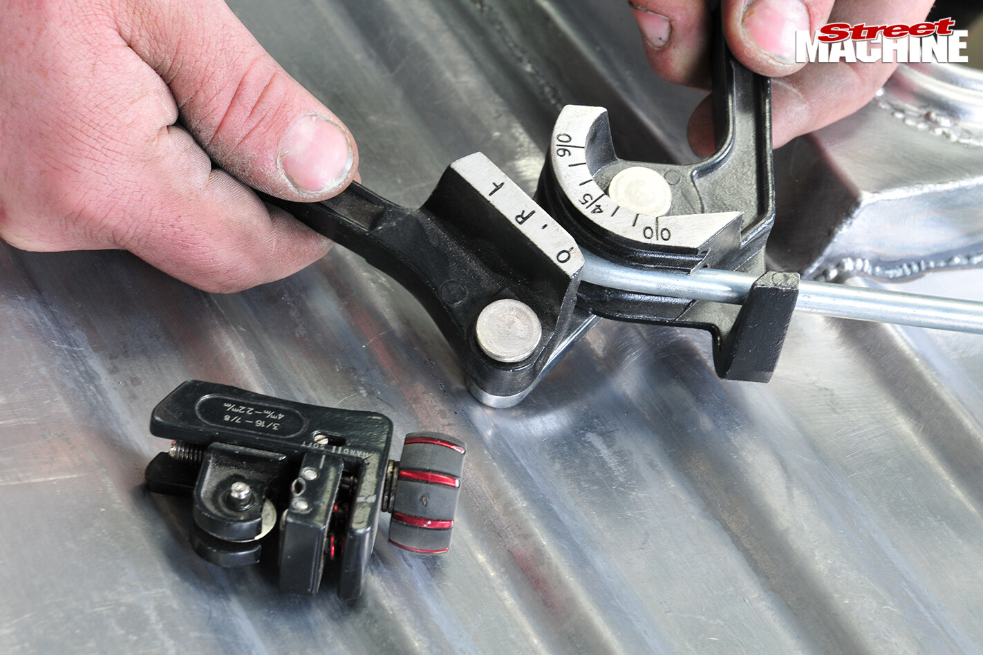
New bundy tube is bent to form and then flared using a double flaring tool at the hose end, to create an annular bead that prevents the hose slipping off
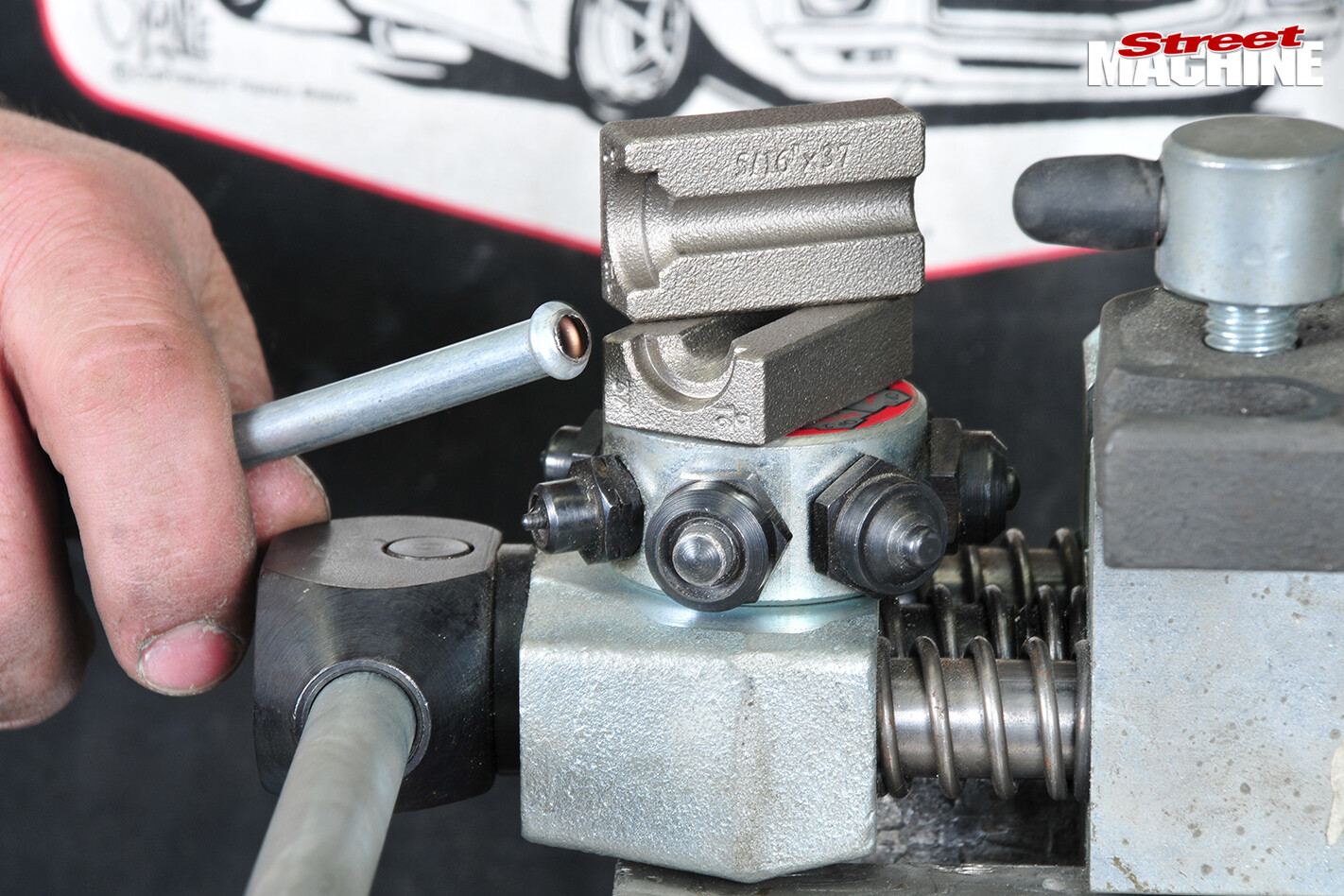 This tool is used because a single-flare kit will make a sharp funnel rather than the smooth bulbous shape you need to keep the hose attached
STEP 4
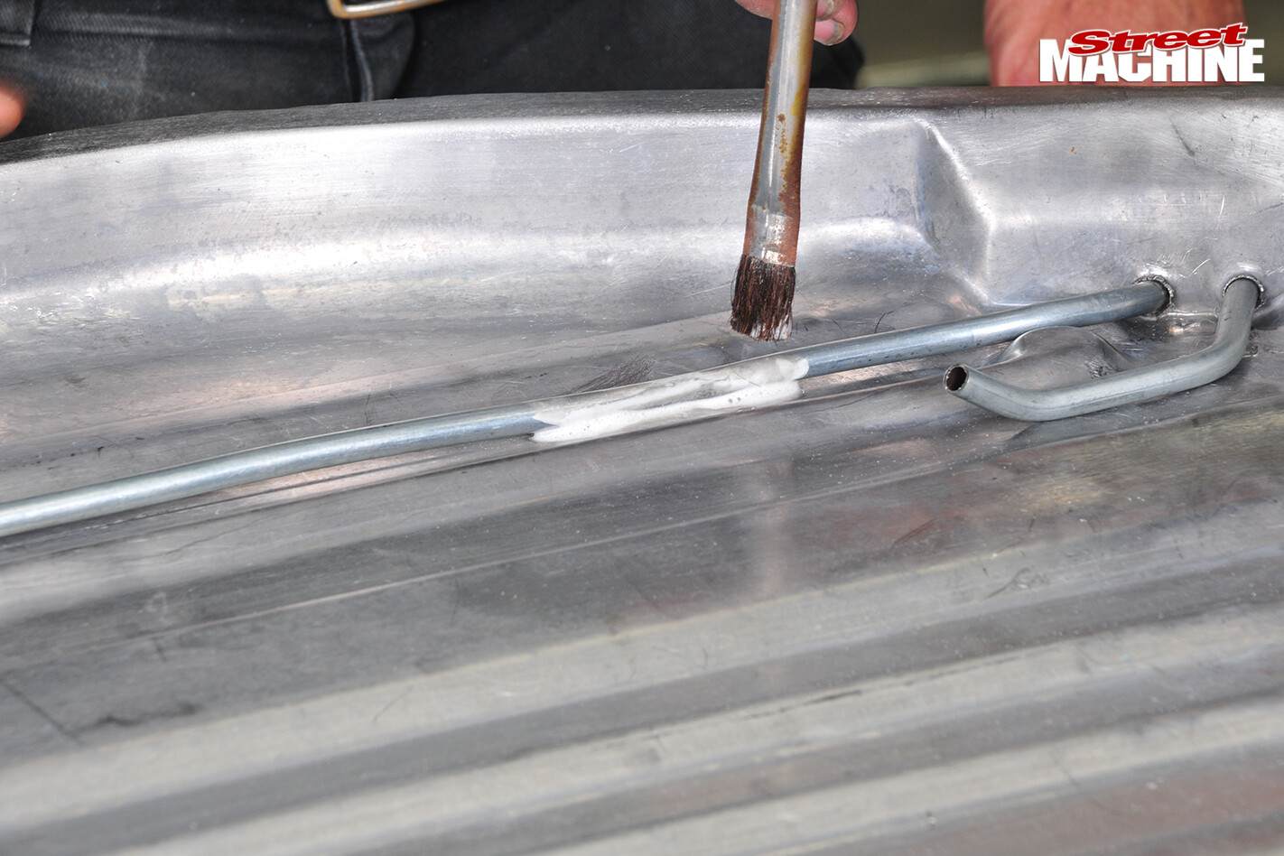
The breather tubes are soldered in place using furnace-heated copper irons
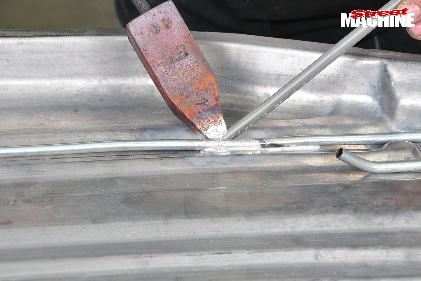 The surfaces have to be thoroughly cleaned with a wire brush, pre-treated with hydrochloric acid, followed by Bakers soldering fluid. There’s still residual solder from the factory, but more is added as shown
STEP 5
Making the spacer strip involves cutting a strip of steel sheet to the appropriate width, folding up one edge to create a flange that matches the width of the tank flange, and then stretching corners to match the tank shape using a stretching machine to make the bends
STEP 6
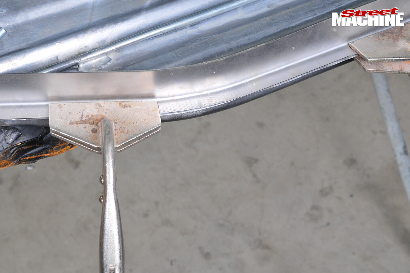
The spacer strip is clamped to the upper half of the fuel tank, taking care to match the shape of the factory flange
 The straight unfolded edge will be butt-welded to the bottom half of the tank, which has already had its flange removed
STEP 7
The factory sender is still being used but the boys have welded in this box section to create a flat mounting service, which helps with the pump installation. However, now the orientation of the sender is wrong, so a bit of work is needed to reorient it so that it works properly
STEP 8
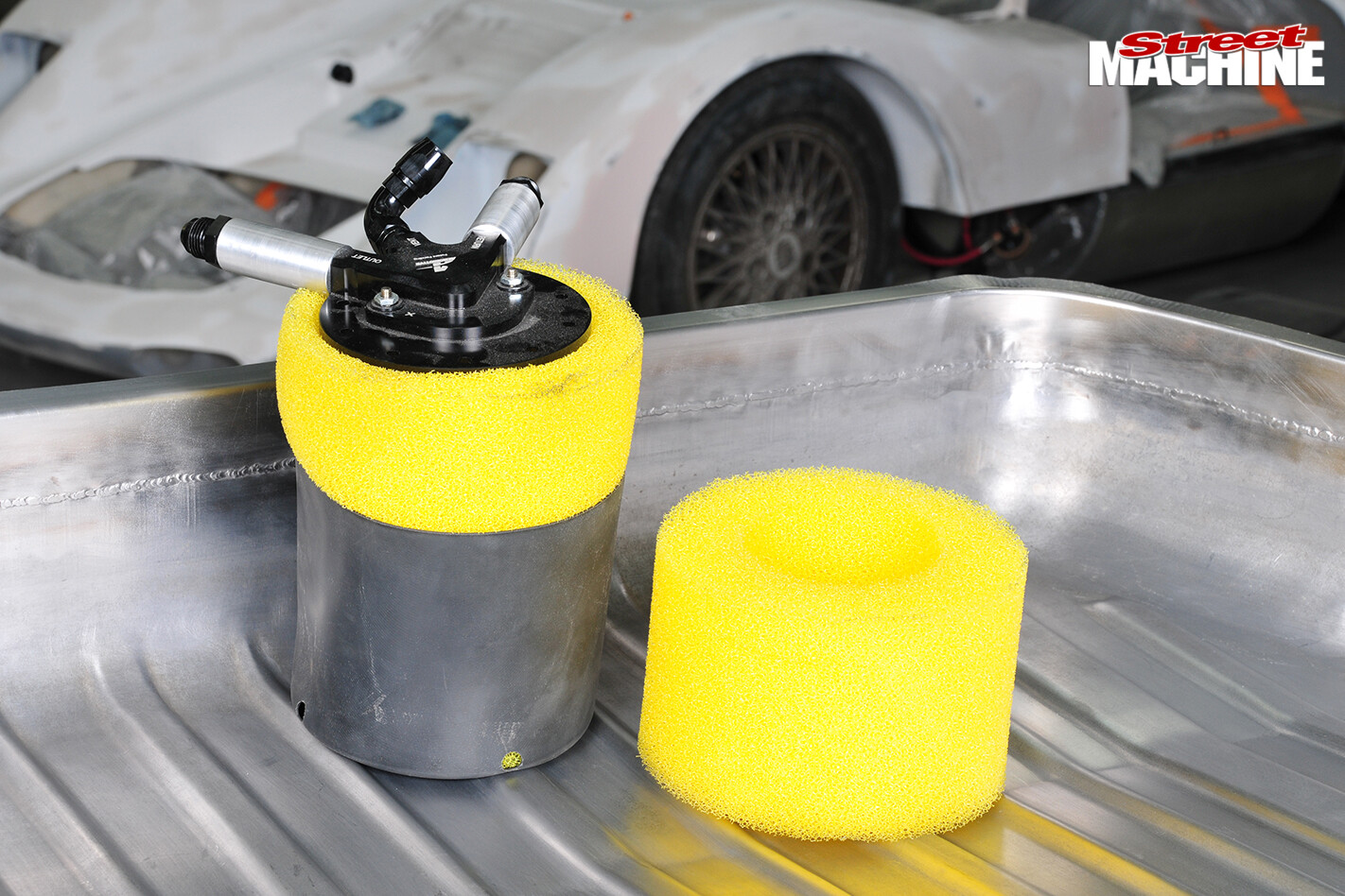
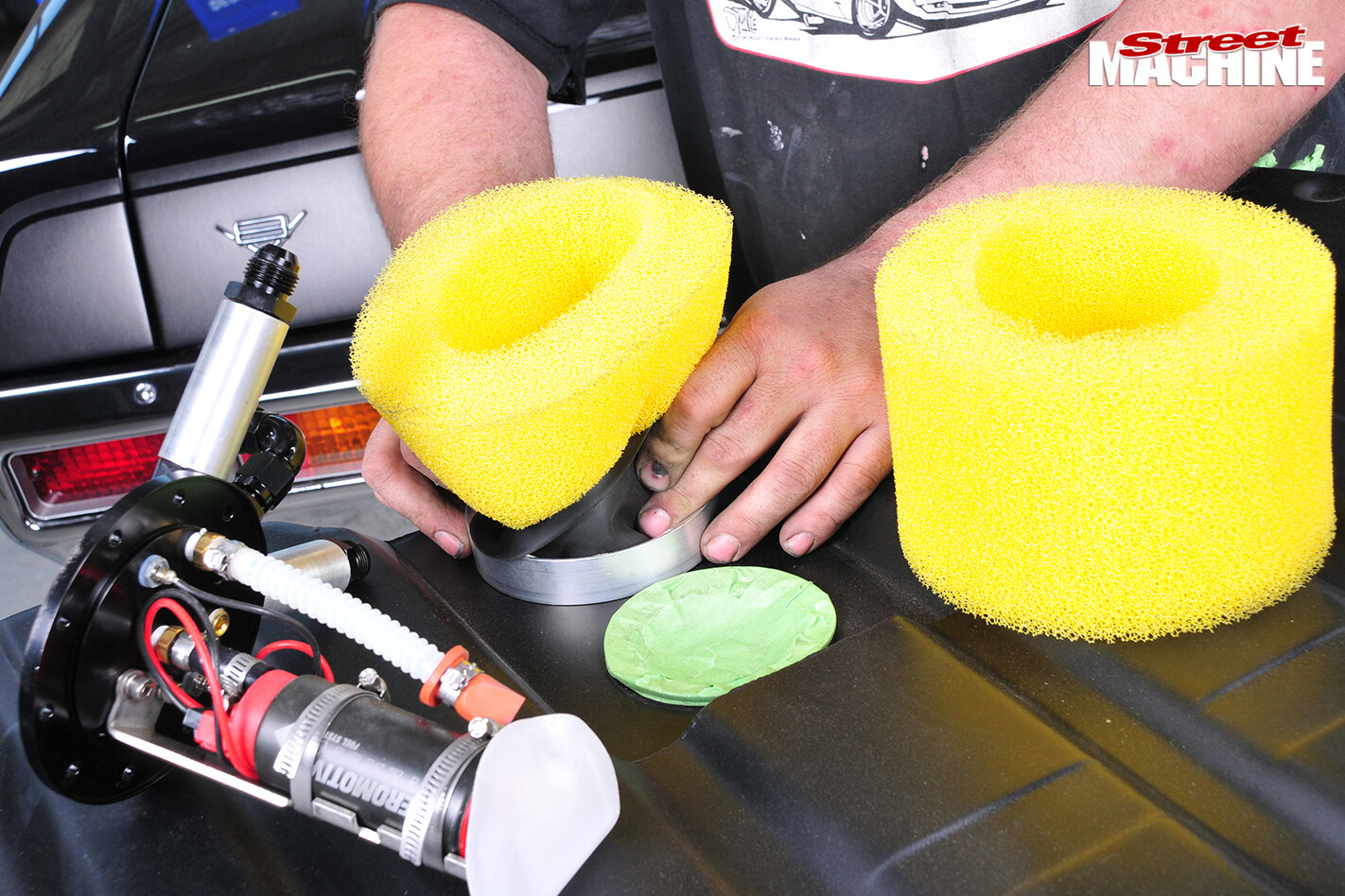
These Aeromotive pumps are supplied with enough foam to reach the bottom of any practical tank depth. The excess foam is simply trimmed off to fit the application. The pump is contained within the foam and this fuel-resistant bladder/basket, which keeps fuel at the pick-up until the tank is empty
STEP 9
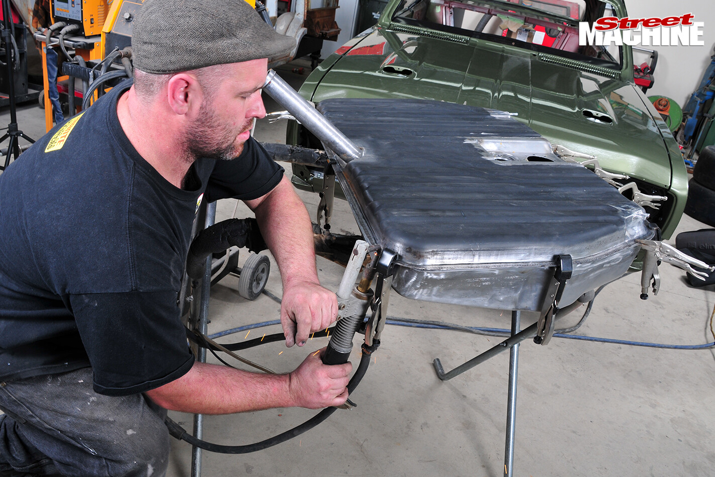
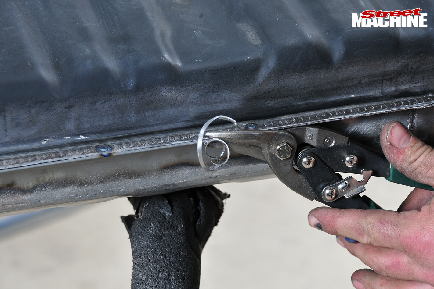
With the spacer strip welded in place it’s time to join the upper and lower halves of the tank. It takes a bit of pushing, hitting, and generally showing it who’s boss to line up the flanges. As the process continues, clamps are applied at the cooperative sections while the others are coerced into place
STEP 10
Spot-welding is used to hold the two halves of the tank together, but it’s not enough to seal it perfectly. Rhys makes some test welds on some scrap material, and if they hold, he proceeds to work his way around the flanges
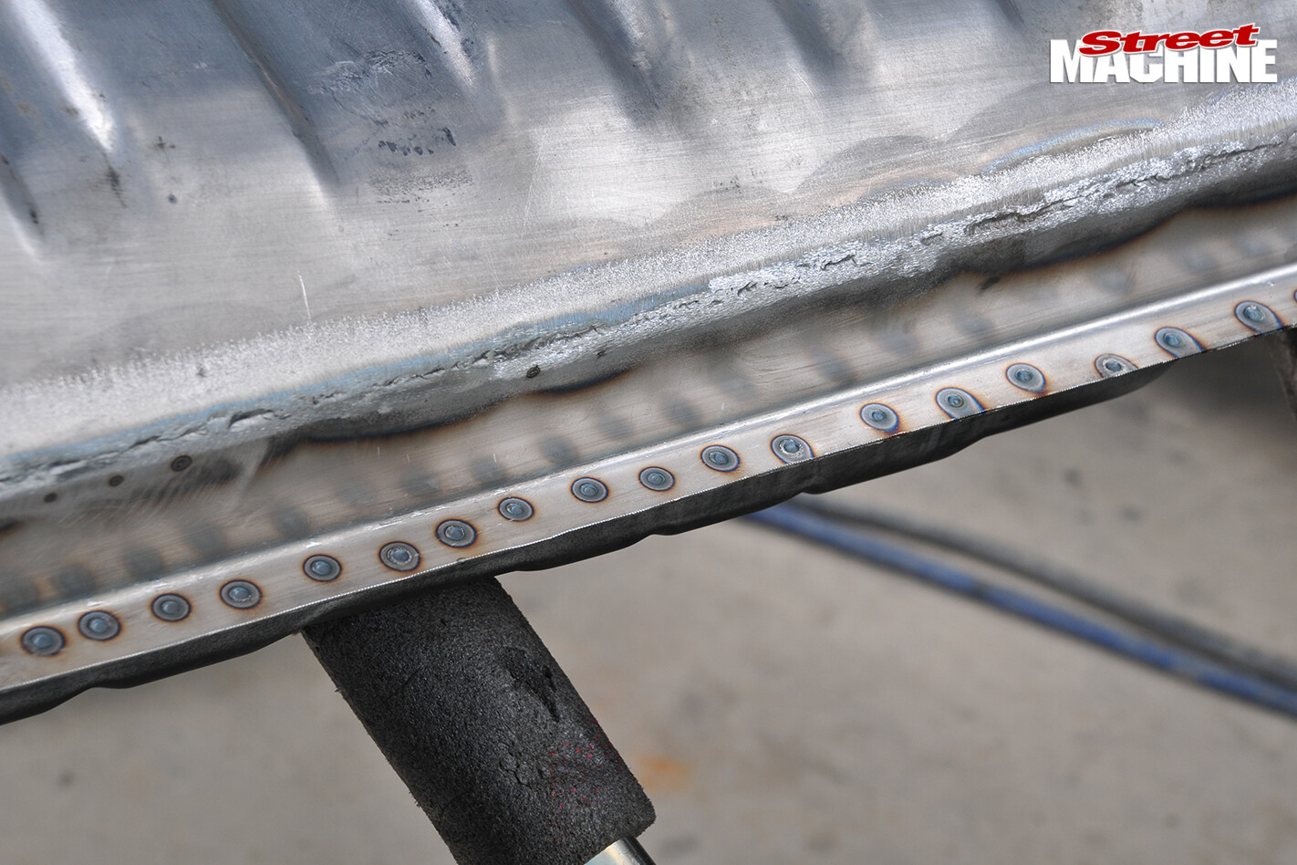
At first the welds are placed around two inches apart; then the clamps are removed and more spots are added
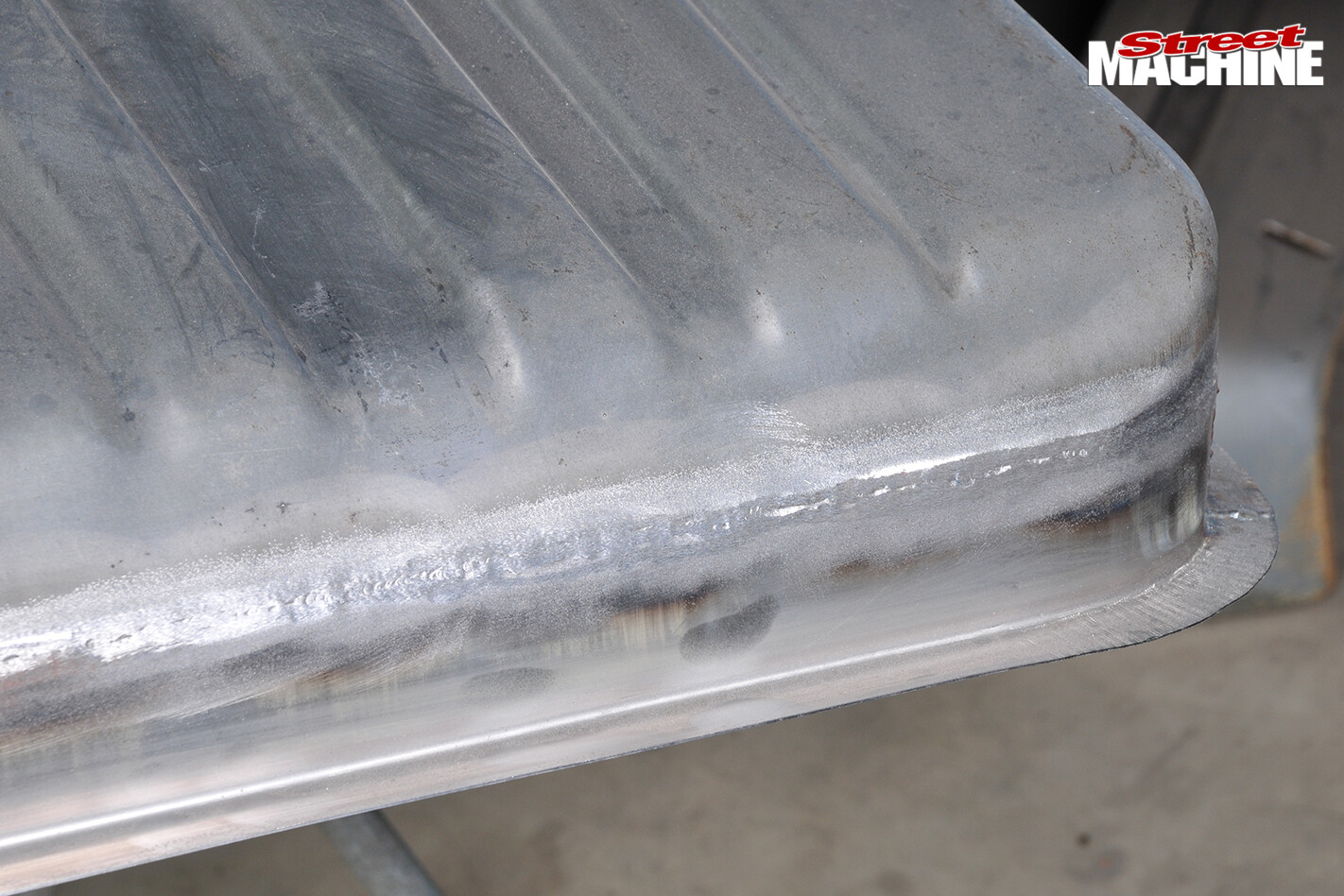
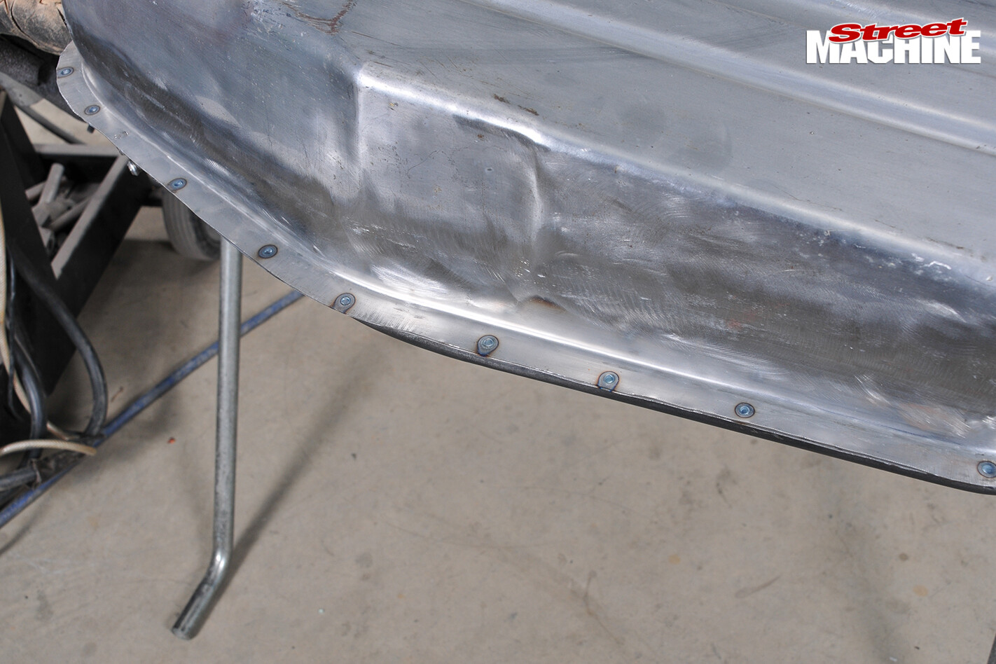
STEP 11
When the spot-welding is complete, the flange edges of the upper and lower sections are trimmed flush and then filed flat and straight to create perfectly aligned edges ready for TIG welding
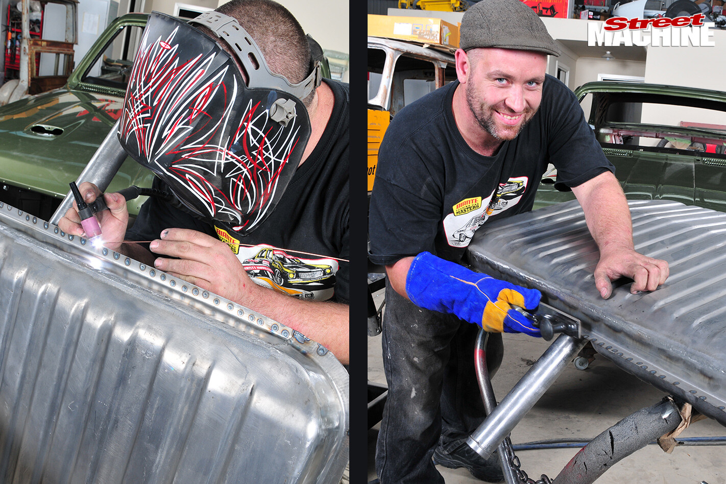
It’s the TIG weld that seals the tank, but every little bit helps, so tank sealing compound is poured into the tank, which is then rotated and rolled until the inside is evenly coated. We weren’t there for that process
STEP 12
Now it’s time for the pump, but the foam and bladder have to be inserted first. They’re both flexible enough to be pushed into the tank through the hole for the pump, but the process is aided by this curved installation ring that comes with the pump
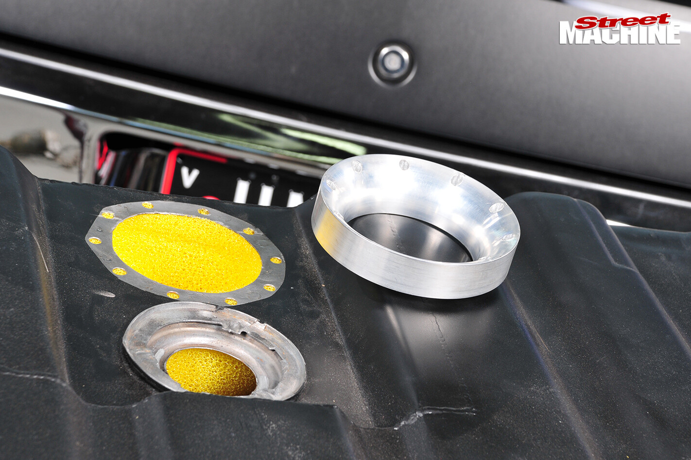
The installation ring also doubles as a template to drill the pump holes
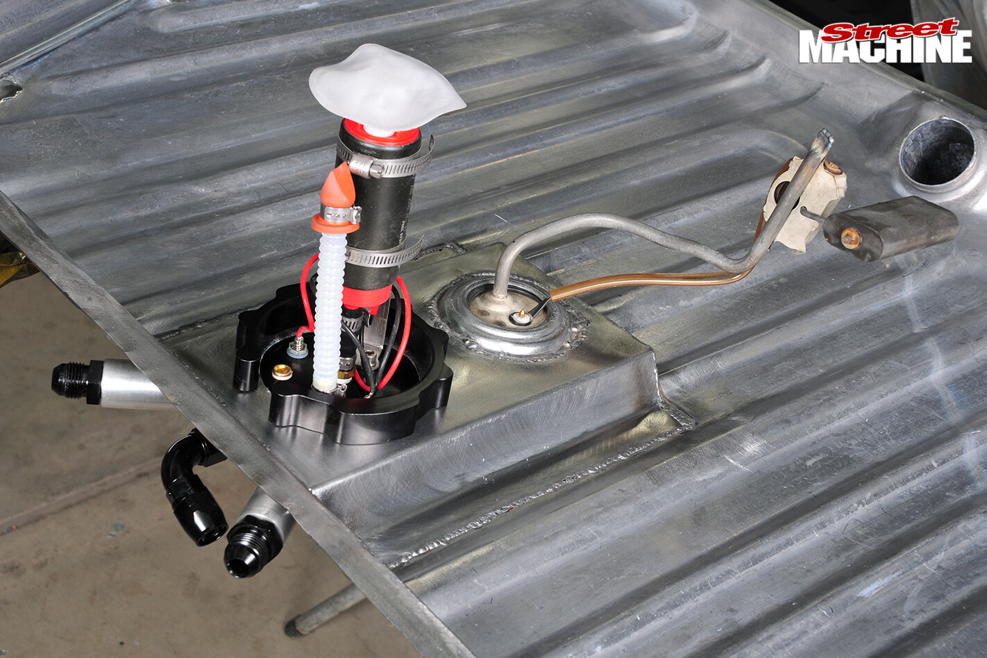
STEP 13
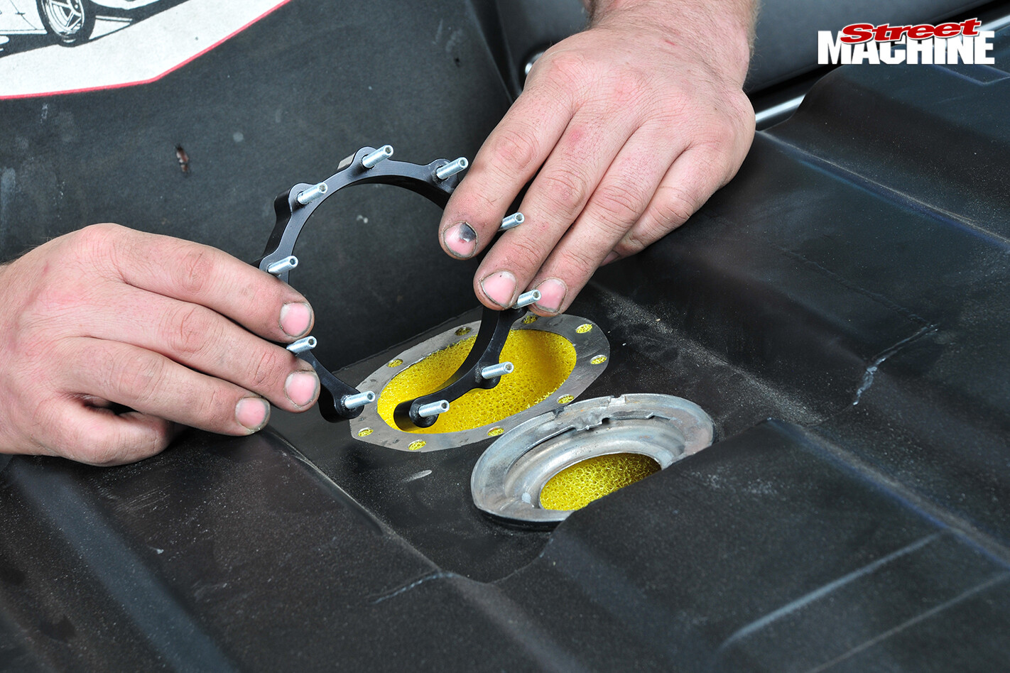
Once the foam is in place the C-retainer ring has to be wrestled into place. It takes some work, but it goes in eventually
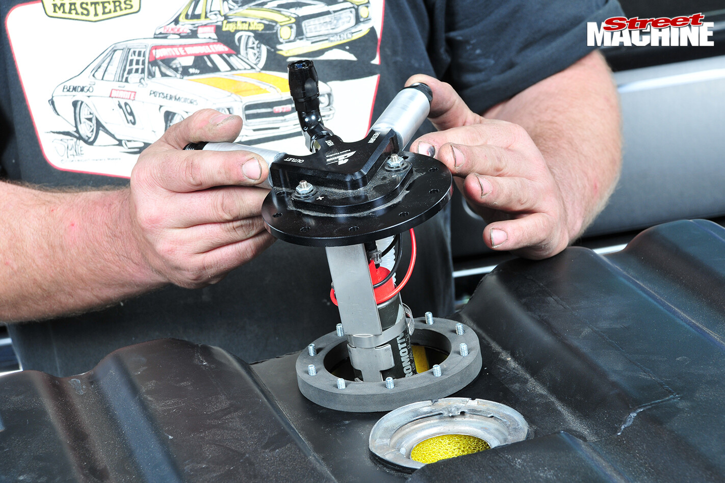
The pump assembly is then lowered into the foam. Note that the pump’s flat steel support strut (toward the camera) can be trimmed to position the pump at the correct height
STEP 14
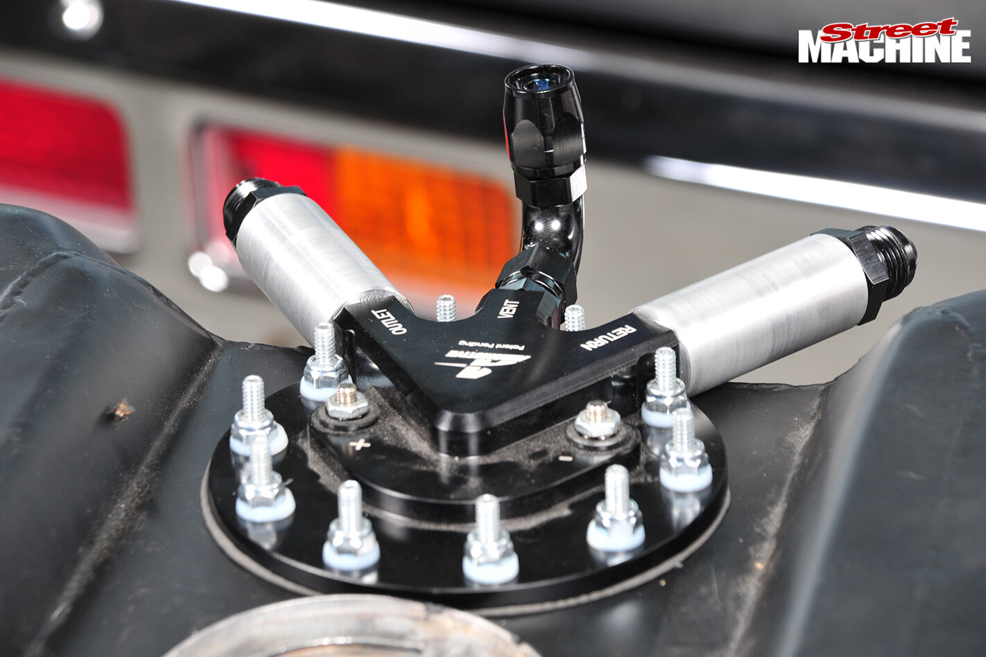
Rhys machined these aluminium connector extensions to clear the tank, deliberately making them a bit longer than needed so they could be shortened to exactly the right length
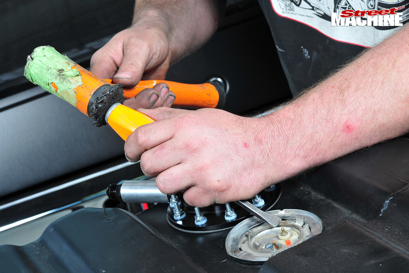
With the pump in place it’s time to re-fit the sender and tap the retainer ring home
STEP 15
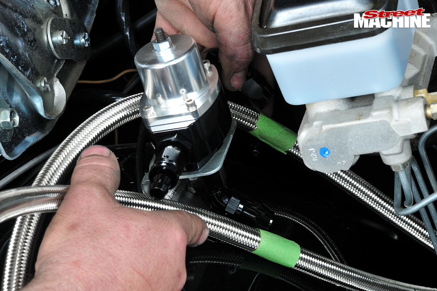
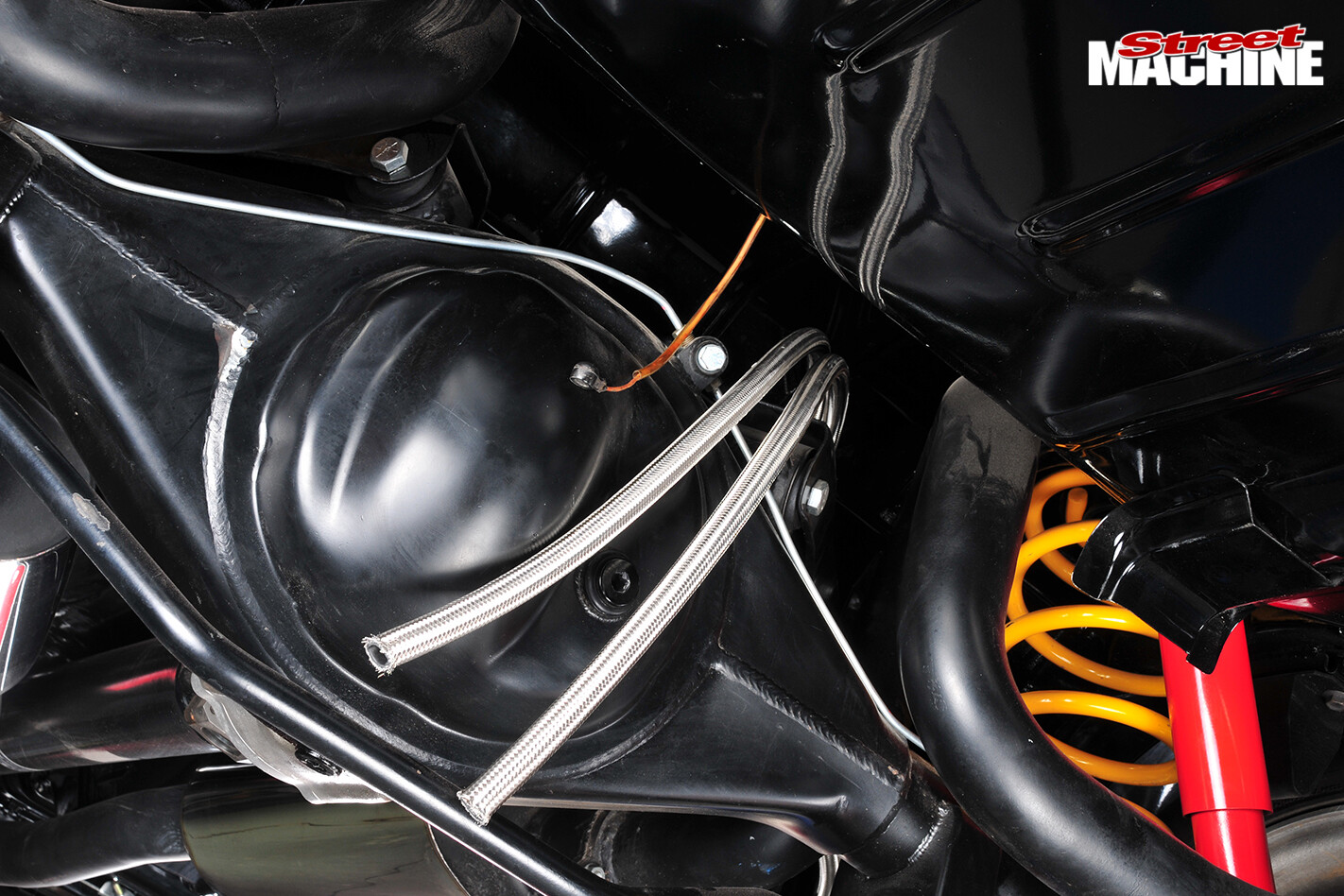
Stainless braided line is functional and good-looking. This –8 (1/2in) line is used for our HQ, and both a feed and return line are needed. It’s best to measure the path the lines will take, double it and then add perhaps another metre to be safe
 Then the cuts are marked and made at the regulator; this leaves a single, long off-cut
STEP 16
Here’s the path Rhys chose for the lines moving backwards from the regulator. Note the neat saddles, brackets and cable ties to hold the lines in place; this stops the braided lines from rubbing and chafing
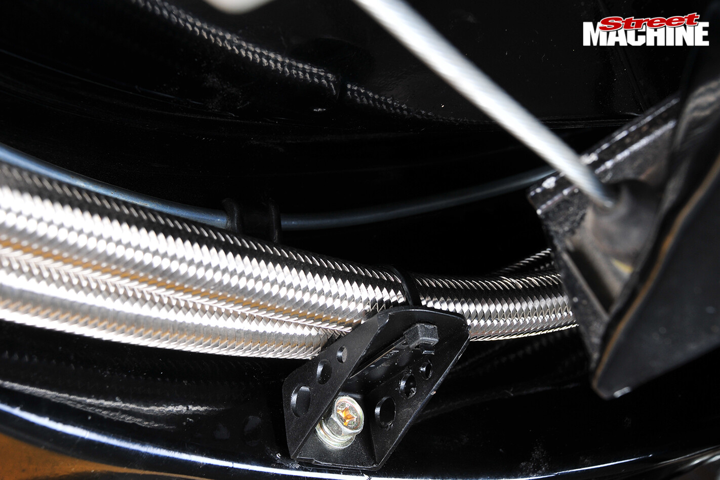
Used properly, cable ties are perfectly fine
STEP 17
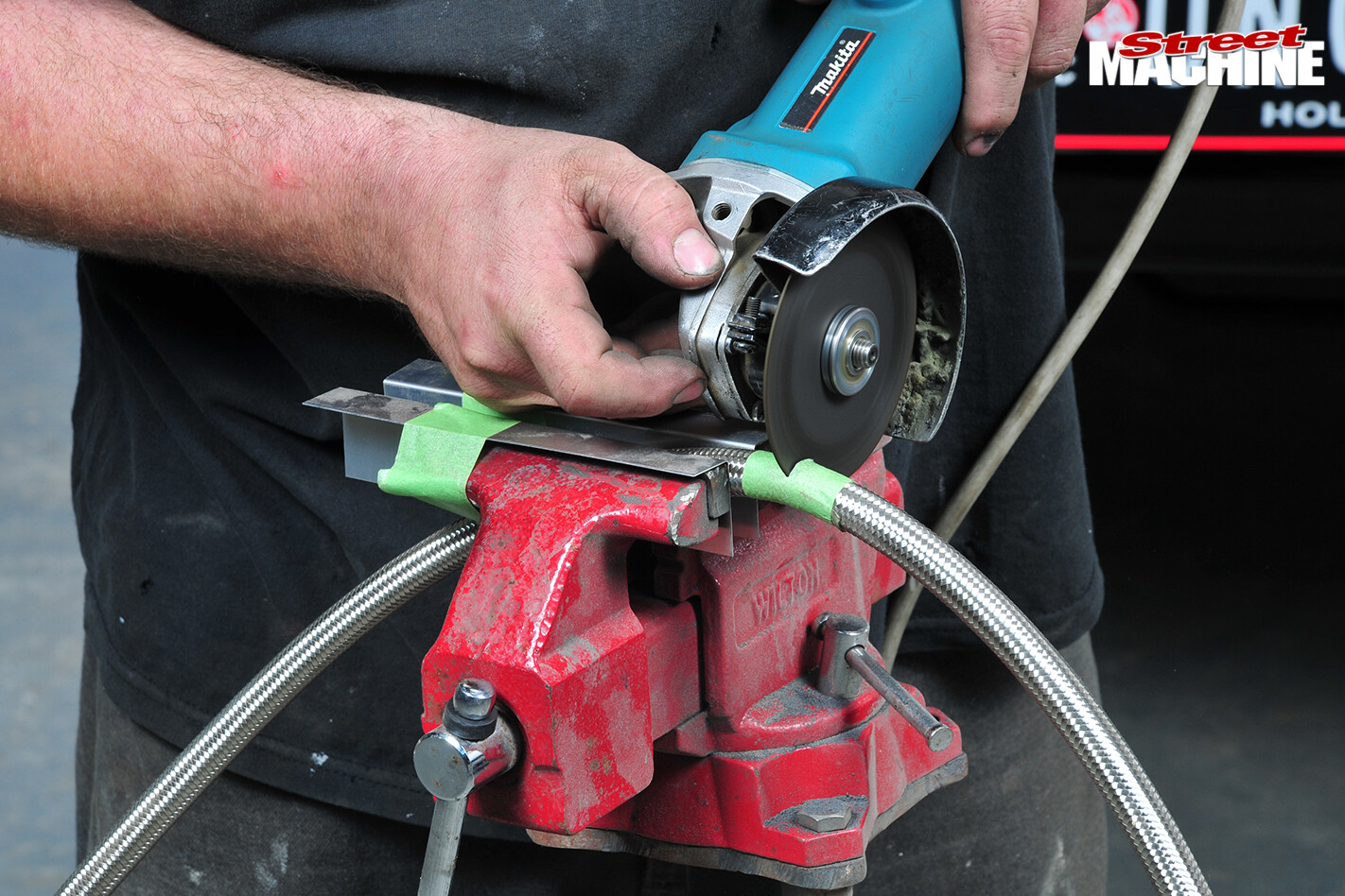
On braided line Rhys likes to tape the point of the cut and use a cut-off wheel as shown. The braid expands pretty much as soon as the tape is removed, which makes it difficult to get the fittings on
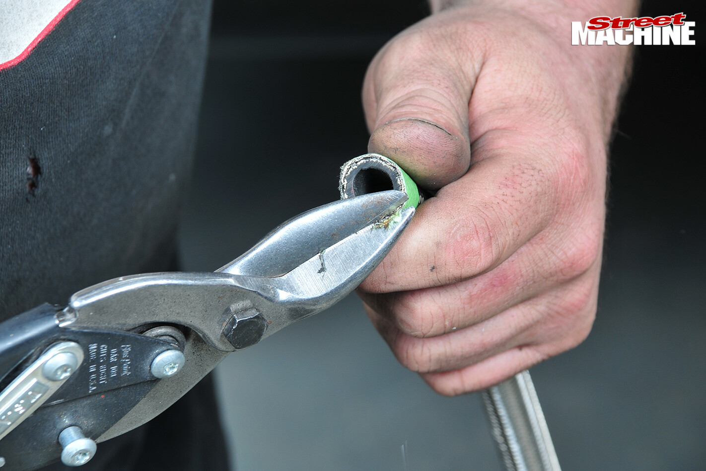 Trimming off the ragged braiding eases things somewhat, but it still takes a bit of effort
STEP 18
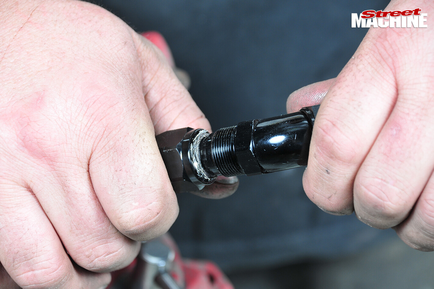
We asked Rhys to show us how to do it by hand. It really is just a matter of sliding on the tightening nut, pushing the fitting into the end of the line until it’s fully home, and tightening it while taking care that the line doesn’t slip back out
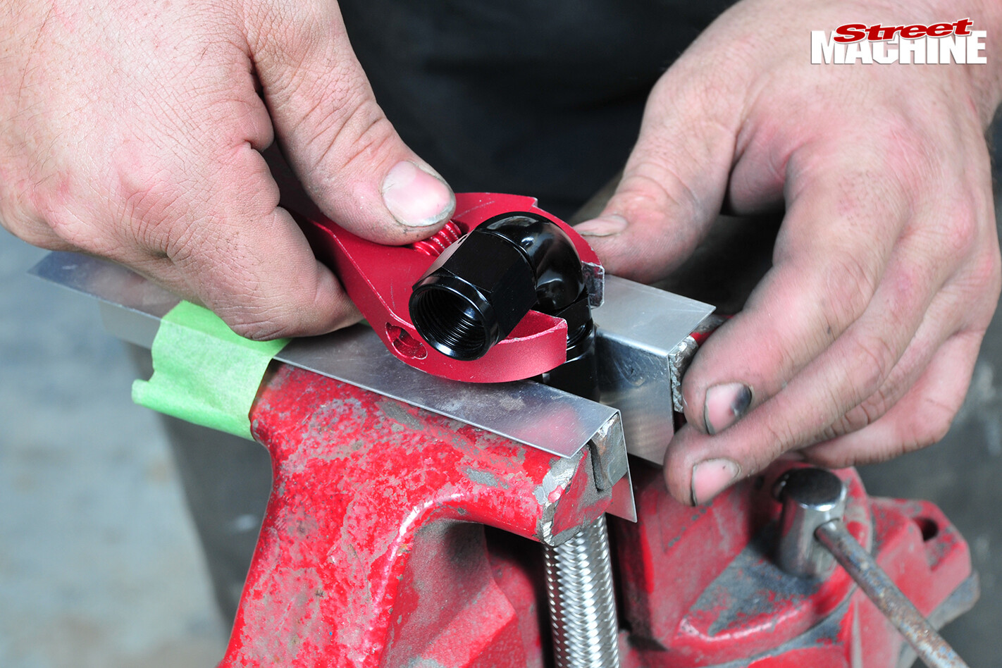 It’s always best to use proper aluminium spanners and vice-jaw covers to avoid marking the fittings
STEP 19
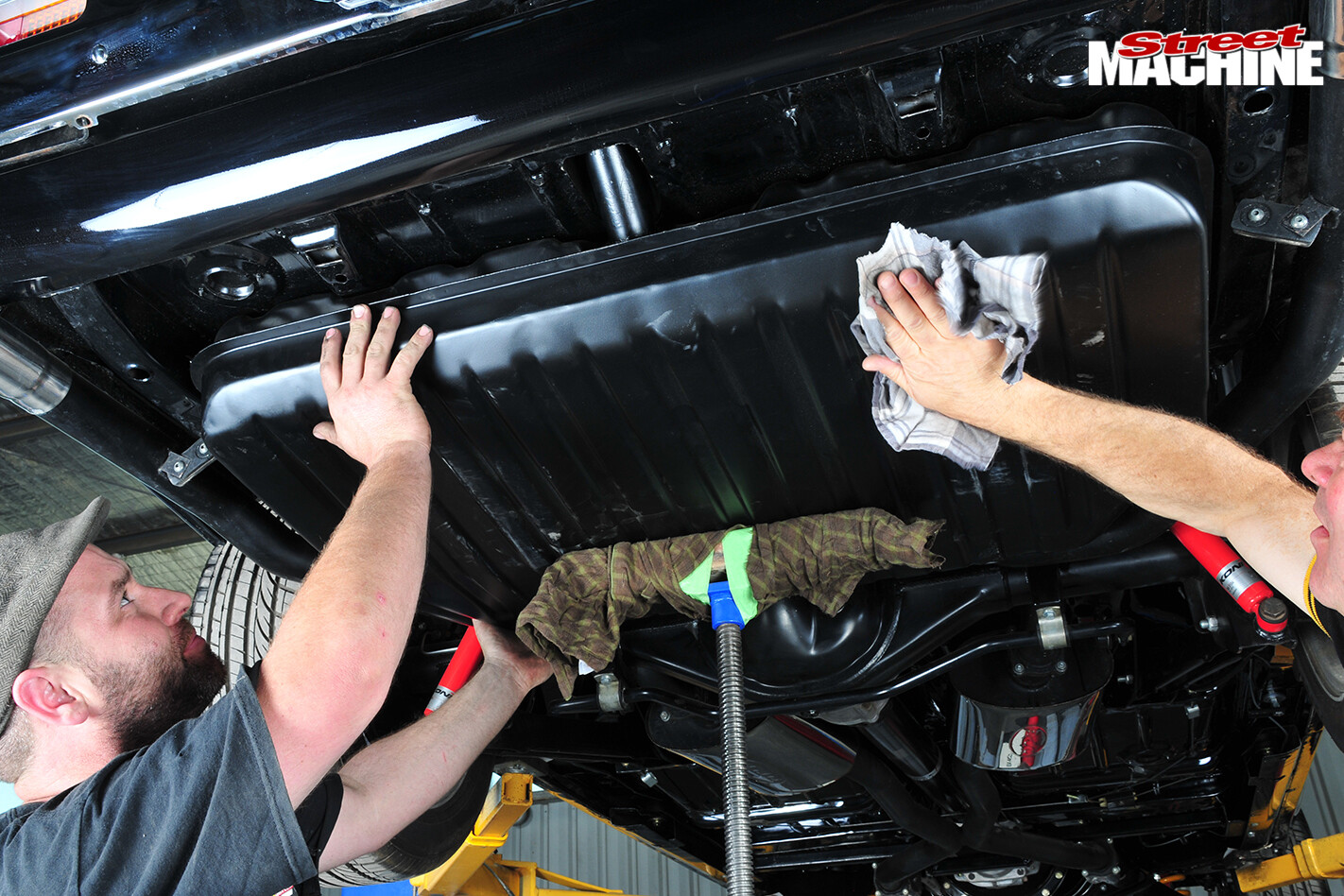
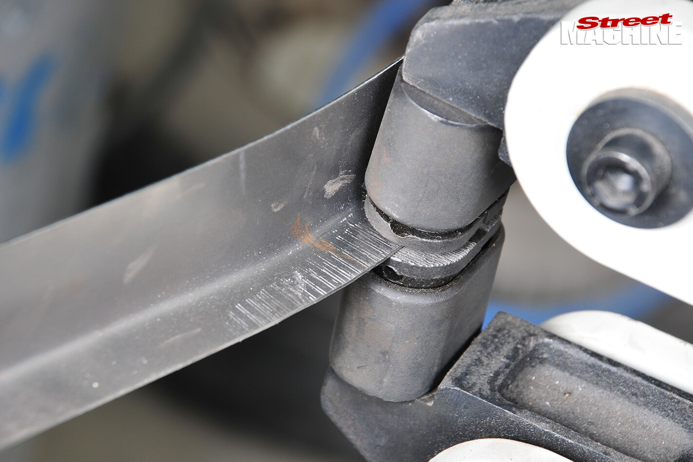
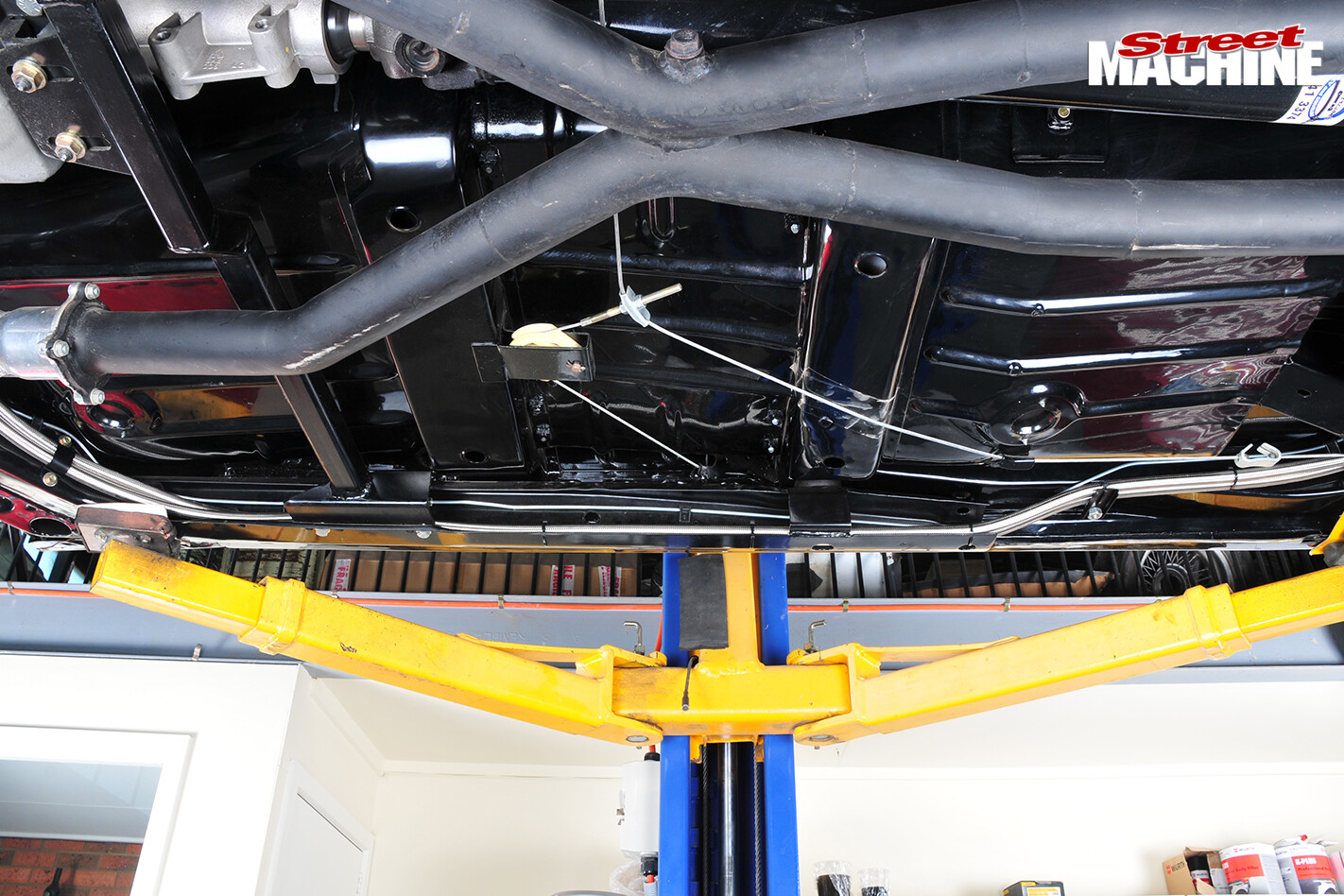
When the lines are completed, the modified tank is fitted. Because the tank has been enlarged, the standard retaining straps aren’t long enough, so they have to be extended
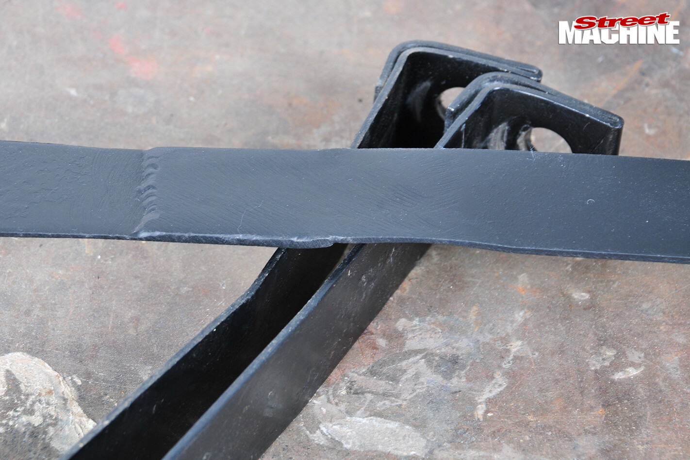 But Rhys points out that it’s not as easy as it sounds, and they can’t be allowed to fail. So two sets of straps are cut to the right length, overlapped and then TIG welded around every exposed edge at the overlap. There’s also a plug weld in the centre
STEP 20
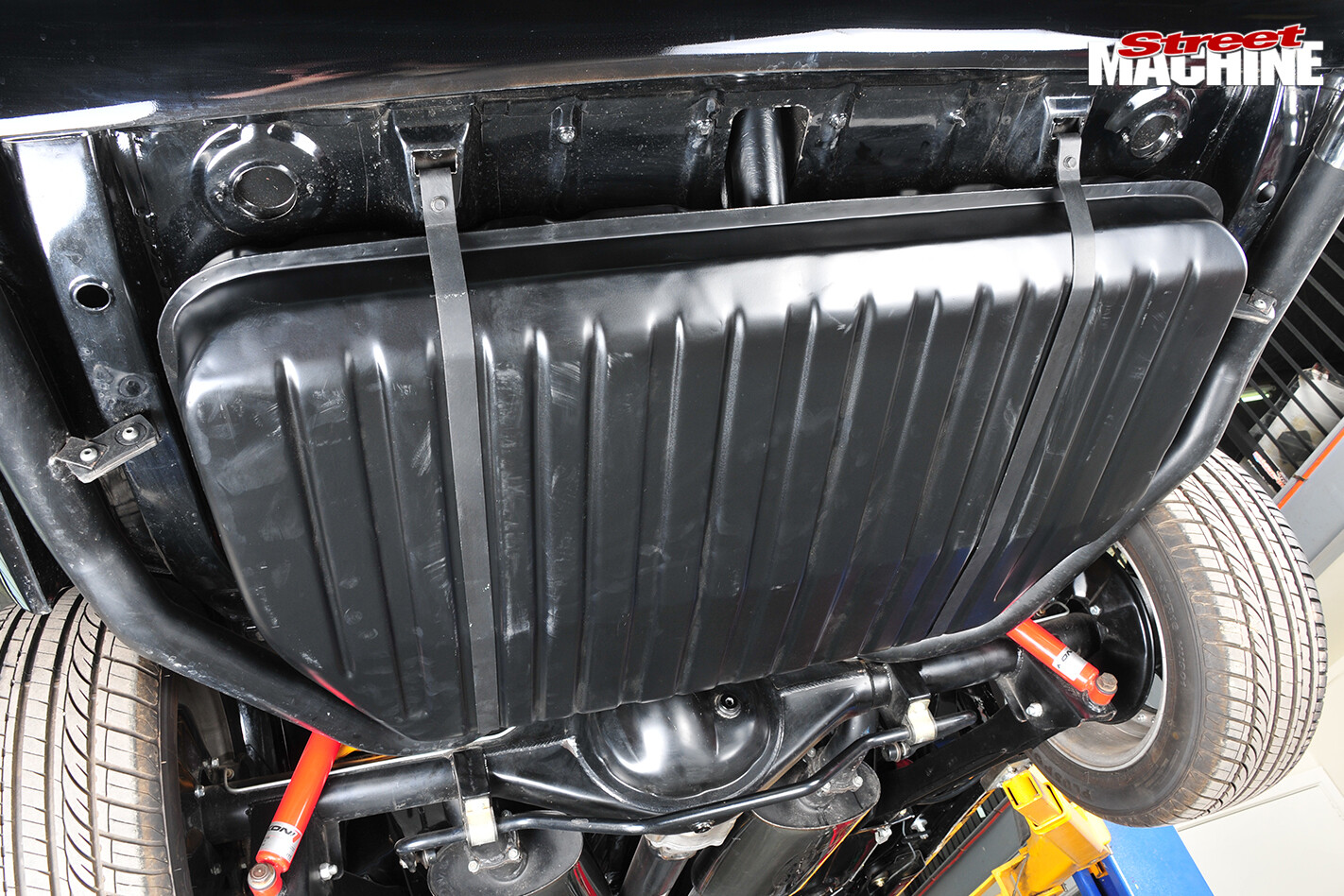
BRMC can supply these tanks as empty change-over units, or as a whole kit including everything shown. We haven’t shown the wiring, but it’s pretty easy and enough instructions are supplied. If you’re interested in knowing more visit their site at www.bendigoretro.com.au or call Gary on 0407 508 989


Comments