Gear
Gallery1
ALL four-wheel drivers like to be as self-sufficient as possible, especially when travelling to the remote regions of Australia. And when you’re there, knowing basic maintenance could save not just a few bucks but possibly even your life.
So join us as we show you how to completely overhaul a live-axle front knuckle and bearing, using basic hand tools. This type of knuckle is similar to what you’ll find under any early Nissan Patrol, Toyota LandCruiser or Land Rover.
STEPS
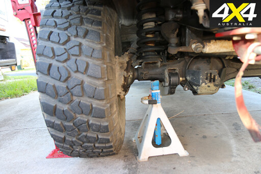 1. BEFORE jacking up the vehicle, chock the opposite wheel and loosen the wheel nuts while the wheel is still grounded. After raising, place a rated jack stand under the axle and lower the vehicle onto the stand. Before taking the wheel nuts and wheel off, give the car a decent shake to make sure the jack stand and the position it’s in are secure. Don’t forget the park brake, and make sure you leave the vehicle in gear.
2. ONCE the wheel has been removed, place it underneath the side of the car. If the jack stand fails and you’re underneath it, it’ll stop the car falling all the way to the ground. While it might not be high enough to stop you from being trapped under the car, it might be high enough to stop you from being crushed by the weight of the car.
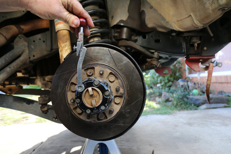
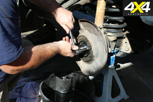
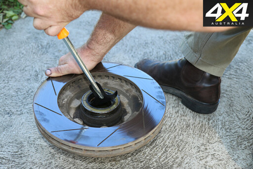
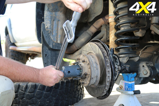
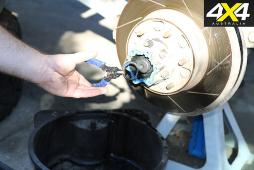 3/4. REMOVE the brake caliper and secure it out of the way – a zip tie works great for this, just make sure you don’t twist or stretch the flexible brake line. Unbolt the freewheeling hub cover then remove the snap ring. To remove it, use a couple of small flat-head screwdrivers – although a pair of snap-ring pliers (pictured) will make the job easier and a lot less bloody.
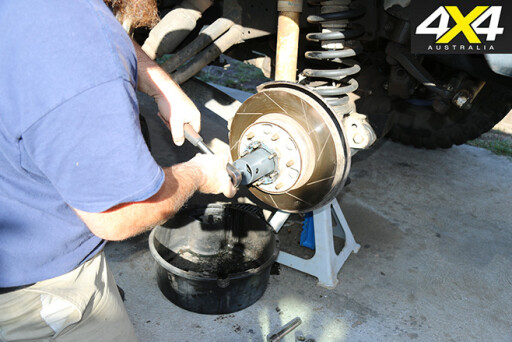
5. TO unbolt the freewheeling hub body, the cone washer must be removed. To remove, place a brass drift onto the end of the stud and strike sharply with a hammer. Sometimes they’ll pop right out and sometimes they’ll have you hammering on the end of the brass drift like your life depends on it. Don’t fall into the trap of hitting the edge of the freewheeling body just above the cone socket – while this will work, it’ll distort the taper and the cone washer won’t be able to do its job of locking onto the stud when it’s time to reinstall it.
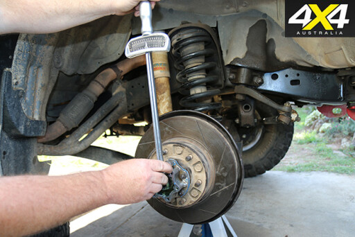
 6. TIME to grab a 54mm socket and remove the lock nut, tab washer and bearing adjustment nut. Some bearing adjustment nuts will have screws; others, as in this case, have a couple of small Allen bolts that will need removal before you can get to the outer bearing. These large 54mm sockets are available at all good 4WD accessory shops.
7/8. TAKE out the thrust washer along with the outer bearing. Then carefully remove the hub and rotor assembly and place it out of the way until later.
 9. SPRINDLE bolts come next – an old ice cream container is a great receptacle to contain the growing number of parts.
10. REMOVE the dust seal and cover to reveal the spindle. To break the seal, the spindle usually requires a little gentle persuasion with a soft hammer.
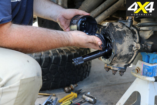
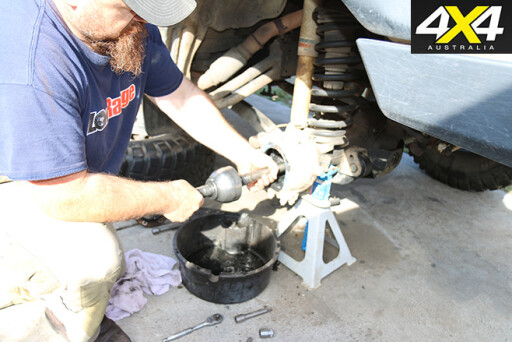 11. GENTLY remove the CV. Some will have a flat ground spot on the bell and require turning to match the opening in the knuckle. When removing, support either side of the CV to avoid damaging the inner axle seal.
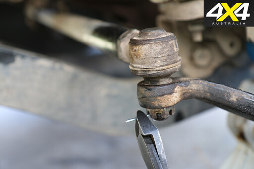
12. REMOVE the split pin and unscrew the castellated nut on the knuckle arm. The rod end is locked into the knuckle arm with a taper, so use a tie rod tool to break the taper.
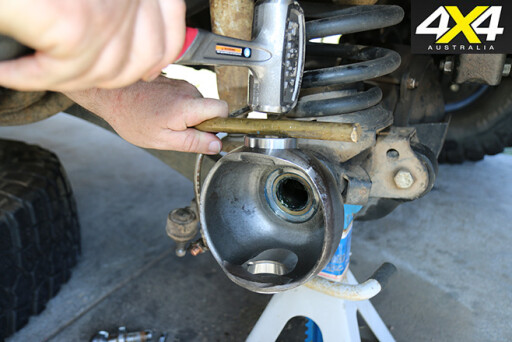
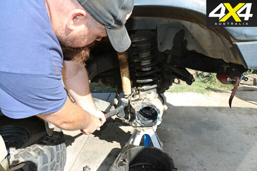 13. THE knuckle arm is held in with four bolts and associated cone washers that all need to come out. Unscrew all four nuts to the end of the stud and then use a soft hammer to give the knuckle arm a couple of sharp blows to dislodge the cone washers without having to chase them across the floor. On the opposite side of the knuckle, the bearing cap will have to be removed. There is a spacing shim in between the bearing cap and the knuckle body, used to adjust the preload on the bearings.
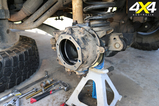
14. THE rear wipers are held in by bolts through to the rear of the knuckle. Removing these will enable the removal of the knuckle.
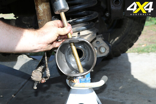 15. AFTER wiping down the bare knuckle, grab out the brass drift and drive out the upper and lower knuckle bearings’ race outers.
16. A SEAL removal tool will make light work of removing the inner axle seal. However, a flat-bladed screwdriver, a hammer and a pair of channel locks will make a decent substitute if you find yourself stranded trackside.
 17. GRAB the hub brake rotor assembly and remove the rear hub seal, using the seal remover and the inner bearing.
18. TO install the new inner axle seal use a special installation tool, or grab a tow ball to use as a mandrel and gently knock the new seal in until it’s seated. Set the seal by packing bearing grease behind it – this will help retain the small spring and keep the axle a little more concentric when you’re inserting the axle and CV.
 19/20. TO make sure you don’t spoil the surface, seat the new upper and lower bearings using a brass drift. It’s imperative that the bearing outers are fully seated.
21. DRAPE the knuckle wiper assembly over the knuckle and make sure it is in the correct order. There may be a small circumferential ridge on the rubber gasket, which will need to face a felt wiper. A little trick that helps keep dust and mud out of the inner working of the knuckle is to saturate the felt wiper with bearing grease before installation.
Spend the next hour or so up to your elbows in kerosene, scrubbing all the bits and pieces. Make sure all of the grease and any silicon sealants are completely removed. Kerosene leaves a residue when it dries, so grab some methylated spirits and wipe any gasket surfaces clean before laying down a small amount of gasket sealant and the gaskets.
 22. PACK the upper and lower bearings with moly grease and install along with the knuckle arm and the bearing cap. Tension the bolts to factory specifications; otherwise the wheel could drop off. If you’ve used quality bearings there should be no need to adjust the shim spacer located between the bearing cap and the knuckle housing. If the preload needs adjusting, refer to your factory service manual to measure the preload and adjust the shims to achieve the correct preload.
23. INSTALL the wiper assembly. The bolts holding the wiper in are small, so use a torque wrench to achieve the correct torque or you risk snapping them.
 24. INSTALL the castellated nut and split pin. Tighten up the castellated nut and then, once tight, move slightly until the hole in the thread lines up with one of the slots in the nuts, allowing you to install the pin. Trim the pin to size and bend the ends over to oppose each other.
25. INSERT the CV, taking care to pack as much moly grease into the rear of the CV bell as you can. Work back and forth to get into all the nook and crannies. If the inner axle wasn’t inserting into the CV, pack the centre of the CV with moly grease. Use the inner axle to hydraulically push the moly grease into the inner workings of the CV, before finally installing the inner axle. You might need to rotate the CV assembly slightly to engage the axle spline into the differential.
 26. PACK the remaining moly grease into the knuckle and try to spread it around as evenly as possible.
27. THE spindle will be a light interference fit, so start a couple of bolts opposite each other to help align the spindle before tapping it home with a soft mallet.
 28. REMOVE the alignment bolts and install the brake dust seal and cover. Don’t forget to install the gaskets and torque the bolts to specifications.
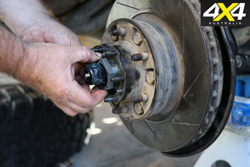
29. INSTALL the inner and outer wheel bearing races in the rotor hub assembly using a hammer and brass drift. It’s imperative to make sure they’re both seated correctly, otherwise the gaps will close with use and the preload on the wheel bearings will be lost, leading to premature failure.
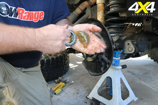 30. TIME to get dirty. Pop a decent-sized wad of bearing grease on the palm of your hand and work it through one side of the bearing until it starts to squeeze out the other side. Work your way around the bearing until it’s completely full. Don’t forget you’ll need to pack both bearings. Once both bearings are installed in the hub, install a new seal into the rear.
31. THE spindle will need a liberal coating of grease before the hub can go back on.
 32/33. PLACE the thrust washer back on, followed by the bearing preload nut.
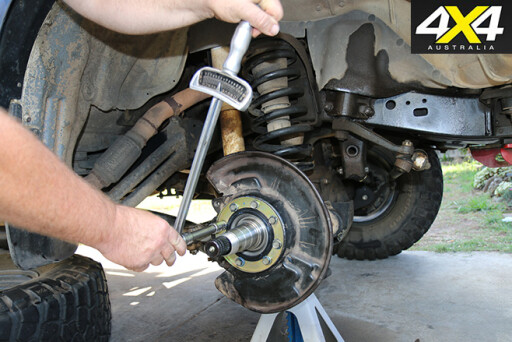
34. IF your 4WD is going to be used for heavy off-roading or thousands of kilometres of corrugated outback roads, you should adjust the bearings. You need to be 100 per cent certain the bearings are seated and aren’t going to lose their preload once set. Tighten the bearing preload nut and use a soft-faced hammer to beat the living snot out of the rotor face while occasionally turning the rotor. Better to do it now than realise there’s a problem half way down the Oodnadatta track.
 35. TIGHTEN the bearing preload nut to the factory service manual’s specification.
36. INSTALL the vehicle’s bearing preload locking mechanism so you don’t lose the setting.
 37. INSTALL the freewheeling hub’s body using the cone washers, flat washers and nuts. Torque to specification.
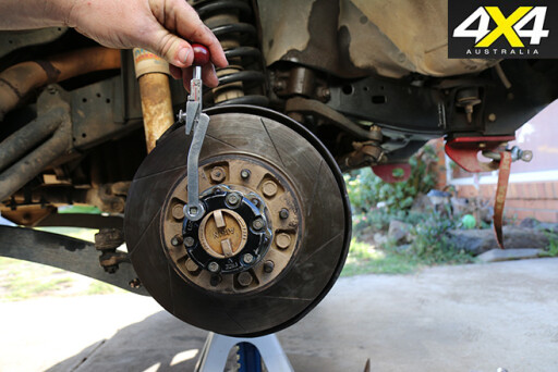
38. CAREFULLY replace the snap ring. Bear in mind it’ll be under tension when you’re installing it, so it’ll shoot off into the darkest corner of your workshop given half an opportunity.
 39. INSTALL the freewheeling hub’s cover and torque to spec. Don’t forget to install the gasket if applicable on your vehicle.
40. REINSTALL the brake caliper. If you didn’t touch the brake pedal while the caliper was off, it should slip straight back on. Make sure the flexible brake line isn’t twisted.
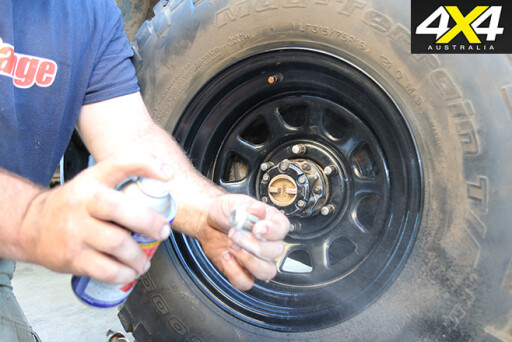 41. PUT the wheel back on. Before installing the nuts give them a little squirt of water-dispersant spray, so that next time they’ll come off nice and easy.
All that’s left now is to jack the car up a little, remove the jack stand and lower the car. Once the car is on the ground, check the tension of the wheel nuts. I like to tighten each opposing nut and count them out loud – it provides amusement for the onlookers if nothing else! Start at the top and re-check the tension of each nut, working your way around in a clockwise direction.
Since I’ve been using this method I haven’t had one wheel overtake me on the freeway. It’s a good idea to re-check the tension after a short drive.
Well, what are you waiting for? Go hit the tracks!
Please enable JavaScript to view the comments powered by Disqus.
COMMENTS